|
|
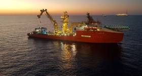
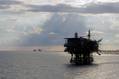
In addition to allowing cranes to work safely and effectively in harsh conditions, heave compensation reduces the effect of resonance on the subsea load. Photo from Huisman. |
Accurately placing heavy loads in inclement conditions offshore is a major challenge, and it is compounded when installation activity is taking place in deepwater. Rough wind and weather conditions can test the limits of installation systems, often resulting in downtime and sometimes causing damage to vessels, cranes, winches and associated lifting appliance equipment.
Growth in the subsea sector is one of the significant drivers for the focus on crane safety and capabilities in recent years. According to analysts at Infield Systems, global subsea capital expenditure and subsea tree installations are expected to double in the next five years. This growth in the number of subsea installations, coupled with the fact that much of this work will take place in deepwater, will draw even more industry attention to the subject of crane safety.
Changing conditions impact performance
Offshore installations in harsh sea conditions increase the demands on cranes because when a load is being placed on the seabed in demanding environments, excessive dynamic amplification of the load can overload a crane or rupture the hoisting cables. There is a clear need for cranes that are capable of contending safely with the rigorous demands of deepwater operations in challenging seas.
One approach to managing inclement conditions is to employ a heave compensation system – a system that is based on heave motion prediction coupled with an inversion-based control strategy. Heave compensation (also called swell compensation or motion compensation) is an increasingly common approach used in marine lifting and support systems to reduce the effect of vessel heave on a suspended load. The objective is to let a rope-suspended payload track a desired reference trajectory in an earth-fixed frame such that it is not influenced by the heave motion of the ship or vessel.
In addition to allowing cranes to work safely and effectively in harsh conditions, heave compensation reduces the effect of resonance on the subsea load as well as the potential for shock loading during complex lifting operations. Because of the complexity of heave compensation in terms of both design and operation, most classification societies are making provisions in their rules and guidance to address the development of this technology.
Understanding installation demands
To better grasp the value of heave compensation—and the need for it in the offshore lifting industry—it is important first to understand that without heave compensation, a suspended load is subjected to heave motion in line with the vessel; when the vessel rises or falls as a result of a wave, the load on the end of the system moves by the same amount.
This motion poses challenges when the lifting system is maneuvering loads, moving them from one location to another (such as ship to ship or in subsea positioning activities), between vessels and static locations (such as lifting an offshore module onto a static jacket) or when the load must be held in place for a specific operation (such as subsea interconnection work using ROVs).
Managing heave
Typical passive heave compensation (PHC) systems, such as in-line cylinder/sheave systems or hook-mounted pre-pressurized cylinder based systems work like shock absorbers. They are simple closed-loop systems with little or no requirement for an electronic control system. Most PHC systems can be considered failsafe because they do not require an external source of energy to operate.
While PHC systems can dampen the effects of heave (i.e., reduce the effects of resonance during deepwater subsea lifting), they are not as accurate for most operations as active heave compensation (AHC) systems. Most PHC systems require a specific pressure in an accumulator system that is calculated on a load-by-load basis, meaning that new calculations are required for each differing load scenario. PHC typically cannot be used in situations where the load changes, such as in subsea coring activities where the deployed weight is not the same as the recovered weight.
As AHC implies, the compensation system predicts the vessel motions using instrumentation, primarily a motion reference unit (MRU), and operates a system to raise or lower the load so as to reduce or eliminate the vessel heave motion. Typical AHC systems are winch-based or cylinder/sheave based. In some cases, this takes the form of a PHC system with an active element. There also are methods that change the geometry of the overboarding sheave support through the use of a crane boom or A-frame, but this approach is not very common for lifting. It is used much more commonly in personnel transfer systems.
While AHC systems are considered the most effective solution for controlling a load, they require substantially more system complexity to achieve full operation. It is important to understand that AHC cannot simply be added to an existing crane or lifting system. It must be designed into the crane, taking into account such considerations as:
 |
| Left: Active motion compensation. Right: Passive motion compensation. Illustrations from ABS. |
A typical cylinder-based AHC system consists of one or two sets of cylinders, two sets of wire rope sheaves (one static, one moveable), an MRU based control system and an HPU/hydraulic control system, usually including an accumulator bank for kinetic energy storage. One set of sheaves is statically mounted on a support frame, and the other is attached to the cylinder sets. The winch wire is fed from the winch drum, around both sets of sheaves, then to an over-boarding arrangement. The vessel motion is compensated by the two sets of sheaves moving closer together or further apart as dictated by the cylinder systems, which in turn lengthen or shorten the deployed wire rope.
A typical winch-based AHC system consists of a single drum winch, an MRU based control system and an HPU/hydraulic control system (usually including an accumulator bank for kinetic energy storage). Electric drive is gaining popularity where environmental issues are a key design driver, but while electric drive or a mix of hydraulic and electric drive can be use, the most common arrangement is for a purely hydraulic system. The vessel motion is compensated by the rotation of the winch drum controlled by the instrumentation arrangement with input from the dedicated MRU.
There also are geometry-based systems that use cylinders or some other mechanical means of manipulating a mechanism to position a load. As in the PHC and AHC systems, this type of system has an MRU based control system and an HPU/hydraulic control system that usually includes an accumulator bank for kinetic energy storage.
Pushing technology limits
The demand for heave compensation in most areas of lifting operations is providing fertile ground for new technology developments such as fiber rope, battery systems and electrical energy storage.
Fiber rope offers many advantages to heave compensated lifts for deepwater operations because fiber rope is neutrally buoyant. When wire is deployed by a subsea lifting system, the weight of the wire contributes significant additional weight to the hookload, which must be managed by the crane. Using fiber rope reduces the overboard load, which results in both load control and power consumption advantages.
While advances are being made in fiber rope design, lithium ion battery systems are improving in terms of energy density. Today, automotive technology allows for multiple kilowatts of storage in a relatively small battery. Transferring this technology approach to offshore installation operations is allowing the development of subsea AHC lifting systems that can be placed on the seabed instead of aboard a vessel. Locating the lifting system closer to the load nearly eliminates the impact of the deployed wire.
Improvements in short-term energy storage, such as kinetic energy recovery systems (KERS), have great potential for application in AHC systems, specifically in the control and dispersal of regenerated energy in systems with electrical drives. One drawback of AHCs with electrical drive systems is that the typical method of burning off regenerated energy is to use water-cooled resistors, which wastes energy that otherwise could be put back into the supply system. In hydraulic systems, regenerated energy can be stored in accumulators and reinjected into the supply system, thereby reducing overall power requirements. While it has not been achieved to date, it might well be possible to use KERS to mimic this reinjection method for electrical systems, which could widen the acceptance of electric drive for high-power AHC systems.
Contending with challenges
New challenges are becoming evident as more lifting operations adopt and adapt these systems. Such issues include multifall/multipart lift rigging arrangements and catenaries in deepwater lifting operations.
When a lifting arrangement has more than one part or fall of rigging, the relationship between the position of the hook and the length paid out or in by the lift winch is halved. For every 1m (3ft) of wire paid out or in, the hook moves 0.5m (1.5ft). This ratio halves for each additional part or fall of rigging. Because most AHC systems function through lengthening or retracting the lift wire – invariably before the multifall/multipart rigging arrangement – they have to work twice as hard for each part or fall. In general, a typical winch based AHC system is of no real practical use on a system with more than two-part/fall rigging. Currently, multifall/multipart rigging arrangements with more than two falls/parts are compensated using hook-mounted PHC systems. Regardless, PHC is not as accurate or adaptable as AHC.
Another significant challenge is the impact of a naturally occurring catenary in the lift wire of deepwater operations. As has been found on recent >2000m (6560ft) subsea operations, lift wires rarely sit vertically in the water column. Slack in the wire is not eliminated by the weight of the load alone. The bend in the line creates problems for vessel-based compensation systems because when they retract or extend the wire to compensate for vessel heave, a percentage of the movement intended for the hook based load is lost in the slack of the wire. When the system takes up the slack, the result can be sudden jerky motion at the load, shock loading through the system, confusion in the AHC control system and poor synchronization.
Classification requirements evolve
To keep pace with the rise in the use of heave compensation techniques, classification societies are working to provide guidance in key design areas, including:
The role of class services continues to change as the offshore industry advances into deeper water and more exacting operating environments. As E&P activities move into more challenging areas, classification societies will continue to transform to answer the industry’s changing needs. As operating conditions change, the ultimate goals of the class society remain the same – to help increase uptime, improve productivity and safely expedite advances into technology frontiers.

Herman Stolle serves as ABS’s principle engineer for offshore technology and business development, in Rotterdam, where he has responsibility for general issues on offshore lifting appliances and relevant (subsea) crane applications. Stolle has worked in Norway for 17 years in design and management related to offshore cranes and lifting. He attended the Polytechnic Academy in Enschede, The Netherlands.
Lee Screaton is a Houston-based consultant specializing in offshore equipment and handling systems. After more than 20 years of design, operation and management roles in the oil, gas and subsea telecoms industries, he now regularly consults on existing and future equipment designs for both surface and subsea operations. Lee holds a BEng (Honors) in Electronic and Electrical Engineering from Aberdeen University in Scotland.
 Subscribe