As the industry advances into ultra-deepwater, an increasing number of tight tolerance wells require an efficient system for determining early influxes or losses during drilling, tripping, and cementing operations. Scott Hilliard of Statoil and Florian Le Blay, Soufian Berhil and Eric Villard of Geoservices, a Schlumberger company, present a new early detection flow monitoring system and setup for floating rigs.
 |
|
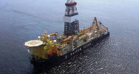
As part of the FLAG service, a Coriolis flowmeter installed in the return flowline continuously measures the actual flow. Photo from Schlumberger. |
With the increase in ultra-deep, high-pressure high-temperature (HPHT) wells, new drilling technologies are crucial. Monitoring active pit volume and the mud level in the flow line are standard ways to detect influx or “kick,” the most dangerous hazard encountered during drilling HPHT wells in ultra-deepwater. However, detecting gains or losses using the active pit is delayed due to the length of the flow line and the communication chain on the rig.
Active pits are commonly located far from the wellhead at the end of the flow line after the gumbo box and shakers. Pit transfers and other operations can influence the volume and require constant communication between the driller, mud loggers, mud engineers, and the derrick man. With the time required for detecting influx and the influence of the communication chain, additional volumes can build up before the decision is made to shut in the well.
Sensor types
The use of the flow paddle on the flow line to detect gains and losses has shortcomings, so in the 1990s, improved flow sensors were introduced on some rigs to measure flow from the well more accurately. Two types of sensors are now common: the electromagnetic sensor and the Coriolis flow sensor.
Although the size and configuration of the electromagnetic sensor make it the best option for flow measurement, being restricted to conductive fluid, or water-base mud (WBM), made the Coriolis flow sensor the preferred option because it works with any kind of drilling fluid.
However the Coriolis flow sensor was rarely used because it required heavy installation and was available only in a small 6in. size. The installed sensor requires a bypass setup. Its small size limits the flow rate by inducing a significant pressure drop that leads to a hydrostatic head before the bypass. This hydrostatic head reduces the flow rate.
The introduction of larger Coriolis sensors in recent years has raised the limit of the maximum flow rate. When combined with an optimized bypass design, these large sensors can be used at very high flow rates for all drilling operations as long as drilling fluid return is directed into the flow line.
Measurement methods
Accurate measurement of return flow is required to obtain well flow, an important factor for monitoring.
Standard measurement methods currently being employed on rigs are mostly achieved using a flow paddle and the active volume. Measurements based on the flow paddle can be easily obtained, but paddle reliability is low due to its mechanical principle and the noisy signal, especially on floating rigs where heave is a significant factor. Moreover, comparing the signal with pump flow rate also is not possible. The accuracy of the measurement from the flow paddle is debatable. The flow paddle provides fluid height measurement, but requires an assumption of the fluid velocity in any attempt to infer a flow rate. Unfortunately, the fluid flow profile can change significantly with fluid properties like density and rheology.
The advanced measurement process in this paper includes many factors that can influence the measurement of actual flow including pump rate, pipe movement, mud compressibility effect, flow line flow back and heave effect.
Differential flow out, which is the difference between actual flow out and theoretical flow out, allows for accurate and quick calculation of the actual volume of the influx or loss without being affected by pit transfers that happen often during drilling.
Early gain detection is the first advantage of using flow measurement at the flow line. Detecting influx as early as possible is crucial to reducing volume and minimizing the risk of an uncontrolled event, or spending time controlling the well.
 |
 |
 |
|
Fig. 1: Comparison flow paddle vs. differential flow out. Images from Statoil and Schlumberger. |
Fig. 2: Comparison pit volume vs. differential flow out. |
Fig. 3: Pipe movement compensation and swab effect. |
Case study
Figures 1, 2 and 3 demonstrate real-time data from a kick event on a sixth generation drillship in 2500m of water drilling a 12¼-inch section. The curves plotted on the charts have been drawn and displayed in real time during a drilling operation in which a kick occurred.
The kick occurred at 7 p.m., the decision to stop the pumps was made at 7:10 p.m., and finally the well was shut in at 7:20 p.m., recording a shut-in casing pressure of 450psi. Some maintenance was performed on the Coriolis sensor during the well control operation, which explains the flow measured by the sensor after the well has been shut in.
Figure 1 compares the measurements of the flow paddle with the differential flow out based on the Coriolis flow sensor. The plot highlights the fact that, if the rig had been equipped with only the flow paddle, it would have been impossible to detect the influx that occurred at 7 p.m. Even when the pumps are stopped, the signal from the flow paddle is not clear enough to determine influx. However, in examining differential flow out, the wellbore obviously began flowing at 7 p.m.
Figure 2 represents the active volume monitoring. This method of gain/loss detection is accurate, but, as shown on the plot, the increase in the pit volume is observed five minutes after the gain was observed on the differential flow out. Considering that the well was flowing at about 35gpm, a five minute delay represented more than four barrels, a significant amount when a gain is considered, especially if the influx is gas. The delay was explained by the fact that the pits were far from the bell nipple, after the gumbo box and the shakers, when the flow sensor was installed farther upstream.
Figure 3 highlights the effect of pipe movement. Once the gain was detected, the decision to stop drilling had been made. When the basic differential flow is considered (flow out–flow in), the decrease of flow out can be seen.
Performing only this calculation to visualize gain or loss flow can lead to the erroneous conclusion that influx has stopped and that the drilling operation can restart without risk. But the decrease of flow out is due to the steel volume of the drill string that was removed from the well while pulling out of the hole.
 |
|
Fig. 4: Accurate real-time gain volume calculation. |
The differential flow out is compensating the steel volume, which demonstrates that the kick is not only occuring, but the kick is actually increasing due to the swabbing effect. The trend of differential flow out is slightly different and highlights an increase of the well flow magnitude.
The other advantage of the processed differential flow out is the compensation of flow back. It is important to consider mud volume in the flow line to accurately evaluate the influx volume and in order to determine the procedure for well control. The active volume presents one disadvantage: Once the well has been shut-in, the measured volume needs to be corrected, including the mud volume in the flow line. This can be achieved by substracting the value of the active volume at the previous connection if it has been long enough to be stable.
This volume also needs to be adjusted by considering the different transfer that could have been performed during drilling. If the trip tank is used to perform the flow check, it should be included. Because differential flow out is not influenced by any transfer and is calibrated to compensate for this flow-back effect, the calculation of the gain volume is done accurately in real time, as shown in Figure 4. This enables decisions to be made more quickly.
Packoff complications
Besides the influx, the packoff also can lead to undesirable consequences, including damage to the formation. Packoff occurs when a plug is formed downhole, primarily at the stabilizer level. This leads to an increase of the pressure on bottom as drilling mud compresses. If the packoff is not released quickly enough, the pressure can reach the fracture pressure of the formation and lead to an injection of drilling fluid by fracturing. When the drilling rig is not equipped with a flowmeter solution, stand pipe pressure (SPP) and downhole torque can help detect packoff.
The packoff event is detected when an increase of torque and SPP is observed while the pump rate remains constant. The differential flow out process introduces the idea of visualizing the compression of the mud and fluid injected in the formation during the event.
Figure 5 presents a packoff event where no damage has been done to the formation. The packoff is building up at 5:01 a.m., as shown by the SPP increase. At that time, the flow out dropped to the booster flow (600gpm). This meant that there was no additional flow from downhole due to packoff. The difference between the flow out and the flow in was the compression of the mud in the drillstring and the annulus up to the packoff.
Once the packoff had been detected, the downhole flow rate was reduced following the established procedure in order to release the plug. As observed on the flow out, after decreasing the downhole flow rate, a gain was noticeable from mud that was compressed when the packoff occurred.
Calculating the cumulative differential flow out allowed for the investigation of whether mud had been lost in the formation. As shown in Figure 5, the cumulative differential volume out was reduced when the mud was compressed to the packoff and increased to 10gal once it had been released.
This 10gal is due to the accuracy of the differential flow out, which was not perfect and the error was cumulated. But this error was negligible when considering that the cumulation was done over 15min. In contrast to the previous case, Figure 6 illustrates a packoff that induced lost fluid.
As noticed during the previous event, when the packoff was building up, the SPP increase could be seen as the flow out decreases. The difference in comparison with the previous case appears once the packoff was released. The flow out returned to normal very slowly and did not show the compressed mud releasing, as was the case previously.
This is explained by the fact that the downhole pressure increased when the packoff occurred and had reached the value that induced the fracture of the formation leading to a fluid loss. In this case, the conclusion can be drawn that the formation had been damaged due to the packoff event.
 |
 |
|
Packoff without formation damage. |
Packoff with formation damage. |
Conclusion
The accurate flow measurement combined with the processed differential flow out method was effective in detecting unplanned events during drilling such as gain, loss and packoff. Beyond the detection, this system enables accurate, real-time calculation of gained or lost mud volumes, which impacts the time required for effective decision making.
Because of the accuracy and reliability of this method, drilling procedures have been adapted that reduce the number of flow checks required at each connection. After the various successful event detections, the decision was made not to perform any flow checks without prior detection by the processed differential flow out, which allows a saving of 10-15 min. at each connection.
This article was prepared based on SPE 158374, presented at the 2012 SPETT Energy Conference and Exhibition held in Port of Spain, Trinidad, June 11-13, 2012.
Scott Hilliard, Lead Drilling Engineer, Statoil, is a licensed Professional Engineer with six years of experience planning and drilling deepwater exploration wells in the Gulf of Mexico. Scott graduated from the University of Texas at Austin with a B.S. in Petroleum Engineering and has been working at Statoil since 2008.
Florian Le Blay has a MSc in Mechanics and Fluids Mechanic from the Centrale Marseille engineer school. Le Blay began working as a Mud Logger/Data Engineer and an Engineer for research and development in 2006. He later became a research and development engineer in charge of the development of the installation of the flow meters on rigs. The last 5 years, he has been a project manager for the early gain and loss detection service. He now serves as the Well Integrity Group Leader in charge of R&D for early gain and loss monitoring and detection service, flow metering data analysis, hole cleaning monitoring and well integrity monitoring software.
Eric Villard is a STEM Corporate Engineering Manager for Geoservices, a Schlumberger company. Eric joined GeoServices in 1992. Eric earned his French Baccalaureate E and later Graduated Engineer from The National Institute for Applied Sciences in Toulouse, France.
Soufian Berhil is a Global Product Champion FLAG for Geoservices, a Schlumberger company. Soufian joined Schlumberger in 2008. Soufian earned his Master degree in Mechanical Engineering from École des Hautes Études d’Ingenieur de Lille in France.
 Subscribe