Designing a tightly packed, complex turret system is one thing. Designing so it can be built and then maintained without causing hiccups is another. Carlo Pellegrino of Italy’s RINA Services explains.
 |
|
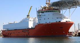
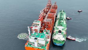
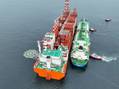
FSRU Toscana. Photos from RINA. |
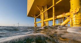
More and more offshore oil and gas solutions tend to be free-swinging floating units as asset owners seek flexibility and solutions to exploit remote and deepwater offshore fields.
These vessels must be moored so they can rotate around a turret system into which all the risers and umbilicals connect.
Turret technology is well-understood and operators have considerable in-service experience of them. However, as units operate in deeper waters, there is a greater requirement for larger numbers of heavier risers and umbilicals to pass through the turret — an already restricted space.
While space congestion can be resolved at a pure design level, with 3D modeling capable of optimizing spaces and preventing physical clashes, such solutions might not take into account how easy and practical it is to build, install and test the turret. A good design, which will work well in service, could be slow, costly and difficult to fabricate, install and test.
Italian classification society RINA is advocating including “constructability” as a design criteria. Constructability is the ease and efficiency of fabricating, installing and testing the main process piping lines, subject to the design and integrity requirements of the installation.
The philosophy behind constructability is to ensure that each system, pipeline and component can be installed and tested in a scheduled sequence without interfering with other systems, pipelines and components.
 |
|
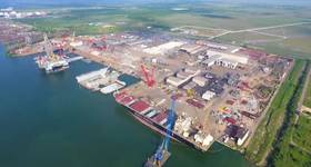
FSRU Toscana. |
Getting constructability wrong can have dramatic consequences for schedules, costs, quality of installations, the ability to remediate defects or construction errors, safety and possibly cause the need to dismantle mechanically completed systems to allow completion, testing or repair of other systems.
For example, in some industry situations, the flange sealing face of large components such as valves were damaged during installation due to poor access or inadequate lifting facilities. As a consequence, the following helium leak test failed and the only solution was to rework the flange face by machining. That meant that, in the restricted space, the installation of the milling machine necessitated a large section of the adjoining piping and related instrumentation to be dismantled. The high-pressure leak test failure introduced an unwanted safety issue, delay to the schedule, and an overall lower quality outcome because brand new items had to be repaired before startup.
Striking a balance
There is a balance to be struck between simplicity of design, efficiency of operation, and ease of building and installation.
This can be achieved by running a constructability study in parallel with the design activities, so that constructability is considered at each phase of detailed design. This process will cover turret fabrication, commissioning and testing, and lead to better overall time keeping, lower costs and higher quality products for the project with a better construction safety record.
Constructability studies should include:
Embedding constructability into the design process requires the use of 3D and 4D modeling tools, such as Autodesk Navisworks and 4D-BIM. 3D modeling software can be fed with information related to both physical clashes and the space allowances necessary for installation and maintenance operations and, with the addition of 4D modeling, scheduling clashes.
Design criteria
 |
|
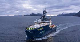
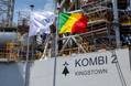
Inside view of a turret. |
Each project also requires its own criteria, such as deck-framing plans designed and placed to support components in place as well as to temporarily support them during installation and replacement, or suitable spaces between components to allow for installation, replacement and maintenance. Another criteria could be that lifting facilities, covering the external and internal areas of the turret, are provided and drop-pick areas are accessible to all lifting equipment. Detailed design should focus on items necessary for easy installation by avoiding the need for extra construction resources, such as highly specialized workmanship or extra lifting equipment.
Inspection strategies and methods must be built into the design criteria. It is useless to build a turret if technicians cannot access it in order to test and inspect it later.
Further detailed design issues that should be built into the 3D modeling process are:
While some of these issues might seem obvious in standard practice, the reality is that constructability objectives are not routinely included in the piping design scope. For example, the design of the piping and valves supports is usually led by the stress analysis results without considering any need for supports to assist component installation and related flanged joint execution. In other words, designers think about the end they want to achieve, not how the builders and testers have to get there.
Fabrication, installation and testing
The selection of fabrication, installation and testing methods and procedures should be focused on easy installation to avoid the need for highly specialized workmanship, extra lifting equipment and for in-field construction, adjustment or reworking.
Some points to consider:
Attention to detail
Constructability is a simple concept to grasp, but a difficult one to implement well, which is why it is too often not given enough priority. It requires meticulous attention to practical details at every stage of the project. That, of course, takes time, money and resources. But it is an investment that pays off by delivering a better turret in a shorter time at a lower overall cost.
 Carlo Pellegrino has 35 years of experience in the oil, gas and energy industry covering QA and QC management positions within several major projects, including responsibility for material reliability and asset integrity particularly with regards to sensitive disciplines like welding, non-destructive testing and materials.
 Subscribe