A deployment system for the installation of large-diameter, reinforced, bonded rubber hose offloading lines for catenary anchor leg mooring buoys has been developed by floating production and mooring systems company SBM Offshore and handling systems specialist Caley Ocean Systems. Caley's Gregor McPherson explains how it works.
Based on a SBM-patented concept, the Trelline Assembly System (TAS) was needed to assemble and deploy lengths of Trelleborg Trelline hose, some of which are fitted with buoyancy modules, from the SBM Offshore installation vesselNormand Installer.
Caley Ocean Systems was contracted to develop and build the SBM concept into a validated design system. The company reviewed the SBM Offshore concept, and developed it into a workable system. This involved working with the SBM Offshore team to refine the hose deployment and lifting system's design, reduce the size and weight of the system's A-frame, and the dual action hydraulic clamping arrangement. While the clamp was able to act as a simple hang off collar to support the catenary during normal operations, it had to provide a 200t clamping mode that could be instantly activated in the event of an emergency.
")
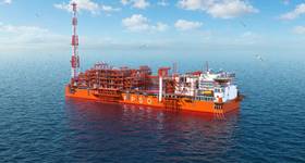
Catenary anchor leg mooring (Calm) buoys are used to both moor a tanker at a single point and transfer crude oil or refined products from a FPSO via the Calm buoy to the tanker, while allowing the tanker to weathervane. The tanker is moored via hawsers and offloaded by means of flexible marine hoses attached to the buoy. Between the FPSO and the Calm buoy, crude is transferred using an oil offloading line (OOL).
Through the development of the TAS, SBM Offshore was looking for a simpler way to assemble and deploy the Trelline bonded flexible offloading hoses which, once assembled, form an OOL connecting the Calm buoy and the FPSO.
Offshore deployment
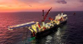
A key requirement of the TAS was that during OOL assembly the hose sections were to be held vertically and launched from the starboard side at the Normand Installer's upper deck. The hose would be deployed using the J-lay principle, going from a vertical position to a horizontal position when launched into the sea. Moreover, the hose deployment system should be able to accommodate several hose sizes (with internal diameters of 18in, 20in and 24in), with up to three buoyancy modules distributed over a single hose segment, facilitating its re-use on multiple projects. Importantly, Caley also had to design the TAS such that it could be dismantled into modular, containerised sections for ease of transportation, storage and mobilisation, enabling significant savings in transport costs and speed of mobilisation.

The TAS system comprises three elements: A-frame lift and assembly, an outrigging assembly platform, and a deployment system passing the OOL from vertical to horizontal onto the sea surface. The TAS system is seafastened onto Normand Installer's deck girders. In ordinary use the handling system is subject to a dynamic load of 25t.
However, in a hose flooding event during deployment, the system could be exposed to loads up to 200t, a higher accidental loading that had to be taken into account.
Each hose section, stored on the main deck and fitted with buoyancy modules, is upended and held vertically above the assembly platform. It is aligned and connected to the assembled Trelline and lowered through the out-rigging platform clamp. To meet certifying requirements, reduce TAS mobilisation times and improve access for operation and maintenance, a Caley standard two-winch system, mounted at deck level, is used to handle the hose section from the horizontal to the vertical. This significantly reduced the size and weight of the A-frame.
Drawing on its experience of handling rigid pipe lengths, Caley suggested a simple guidance system for the hose both above and below the clamp, ensuring a safe and proper alignment of the upended hose and the clamped hose. This ensures the hose is centred as it is passes through the clamp.

In addition, a ‘Diablo' type roller below the clamp was added to prevent the hose from riding up the main sheave as it passes around it. Handle bars are strapped to the bottom part of the upended hose enabling the platform rigger to manually rotate and align the stud bolts with the flange holes of the clamped hose.
The outrigging assembly platform includes the hose friction clamp, guidance system, handrails and walkways. It is designed to withstand the weight of the assembled Trelline, up to 200t, and large enough to accommodate 10 people working together.

The hose friction clamp system is based on Caley's friction clamp design previously used for deepwater J-lay of rigid pipes. It met SBM Offshore's requirements for controlled and safe assembly of the hose segments, held in a vertical position by the hose's integrated bend stiffener collar, and provided an emergency clamping mechanism to hold the hose string in the event it was punctured or damaged.
The clamp comprises a specially designed cylinder that is fitted with an integral high integrity manifold with zero leakage valves. The cylinder is able to withstand lateral (in the line of the hose) loads as well as axial loads. In the event that the clamp has to support a flooded pipe, Caley's leak-free valve system is able to hold the load for at least 24 hours, even with a total loss of power. A further cylinder is used to open the clamp and support the cylinder in the closed position. The cylinders are mounted within a fully machined support frame, located within the main support structure. One of the main drivers behind SBM Offshore's concept was a minimised cycle time, the company having requested that the cycle for hose-to-hose connections should take no more than 30 minutes. Employing the friction clamp makes it possible to reduce cycle times to 20 minutes.

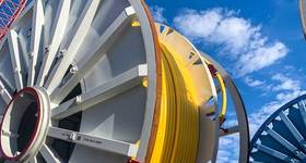
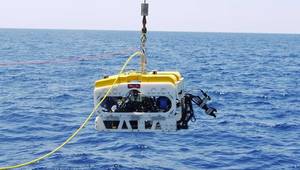
The hose deployment system transfers the OOL from a vertical to a horizontal position and onto the sea surface. The challenge was how to cope with the substantial changes in the diameter of the hose, and attached buoyancy units, as it passed through the guidance gap below the assembly platform and onto the deployment wheel. Immediately below the assembly point, bending of the hose is prevented by applying a vertical loading on the Trelline at the clamping table.
Kinking the hose had to be avoided at all times while maintaining the Trelline within its allowable minimum bending radius (MBR), and simultaneously controlling the deployment of the Trelline onto the water surface. The concept design had featured a 6.0m diameter deployment wheel which was subsequently increased to 6.8m, restraining the hose from bending beyond its MBR.
The deployment wheel is designed to move off its axis of rotation. This ensures that changes in hose diameter, caused by the addition of buoyancy elements, will not impinge on handling operations or cause damage to the Trelline. The change in the relative position of rotation is performed dynamically during deployment, which, although more complex than setting the position of rotation during set-up, provides the highest level of protection to the Trelline.
 TAS deployment wheel for transfer of the assembled hose to the sea surface.")
The hose deployment system was fully tested at Caley's quayside facility, in Glasgow. Scotland, prior to being shipped for integration onboard SBM Offshore's Normand Installer. Following delivery offshore, the TAS system has been successfully deployed for the installation of two offloading lines without any disruption in the assembly process. OE

Gregor McPherson is sales & marketing director of Caley Ocean Systems. A mechanical engineer by profession, he holds an MBA from Glasgow University and has worked in the marine handling equipment sector all his career. He joined Caley in 1994 and was appointed to his current post in 2000.
 Subscribe