Many arguments about the capabilities of a tug can be quickly settled when you can conduct a full-ahead power, bollard pull test.
“Many captains will argue about horsepower, hull design, rudder angles, and other variables, but the only thing that really matters is bollard pull and a test provides empirical data of pure power,” says Mark Babcock, VP of Machinery for Sause Brothers’ 200 tugs, barges and OSVs. “A wellmaintained vessel shouldn’t lose bollard pull over time, but with every propulsionrelated change, engine overhaul, shaft or propeller retrofit, the vessel should be re-tested.”
The bollard pull test has been around for many decades, but recent changes in technique, technology, and data-logging allows engineering and operations to fine tune the analysis and provide more precise information. Providing accurate reports allows pilots, agents and customers to have confidence in towing and tug capabilities at the edge of the performance envelope.
“While many new tugs are built larger and more powerful than ever before, most of the tugs on rivers and ports have years on their engines and the ability to move their tow when it ultimately matters, should be tested against expectations,” said Babcock.
Background
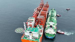
Bollard pull is the static force exerted by a tug at zero speed on a fixed line. Almost always, a test involves affixing a line to a shore-based bollard (a short, vertical post) and ramping the RPMs of the engine to full- throttle, typically in ahead and astern conditions. The vessel is then held at full RPMs between 1 and 10 minutes. Some versions of this test are completed quickly and some, like those in Brazil, last over an hour.
Influences
Many variables can influence a bollard pull test reading, including water depth, prop wash, wind, tidal forces or currents, rudder angle, and stretch of the tow line. Finding an ideal site is difficult, so these external forces must be figured into the final analysis.
Equipment
A bollard pull test requires a tension sensor which is put in series with the tow line, a local display of the line tension, and a process to record that data. Often, an engineer will be present in the engine room to evaluate engine RPMs and another engineer will stand on the back deck to track the forces on the load cell by noting them on a display and manually tracking the figures by hand.
This handwritten process can be challenging and inaccurate in rough weather and in river conditions in which forces on the line change quickly. In river situations, the tug captain may start upriver of the shore-based bollard, bringing the tug up to full power. When the vessel is perpendicular to the shore, the engineer must quickly capture data from the tension sensor. This short time window means it can be challenging to capture accurate data.
Technology advances
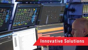
 Measurement Technology NW, based in Seattle, WA, has developed a PC-based software solution that allows data capture up to 100 times per second (Hz). The software time-stamps the incoming data so that it is easy to match up with other data in post-event analysis back at the office, automating and simplifying data correlation.
Recently, MTNW supported the Glosten Associates work with a tugboat bollard pull test in Coos Bay, Oregon. The trials were to test and verify the bollard pull of a number of tugs. “The MTNW tension monitoring system and engineer provided the tension data that we required to perform our analysis,” said Ken Lane, Director of Production Services at Glosten. “The MTNW system captured the line tension data with an accurate time stamp, which allowed us to easily synchronize the tension sensor data with other important measurements.”
 MTNW’s tension monitoring systems include a certified tension link, rugged waterproof local display, and a laptop PC with data-logging software. “The system is plug-and-play for quick set up, allowing for more time testing and lower fuel costs. The engineer can now watch the tension locally, but also know that the data-logging software is catching every tension spike for post-test analysis,” said Tom Rezanka, Vice President MTNW. “The equipment can accommodate tests as simple as full ahead or full astern to the more complicated tests that seek to correlate line tension to engine RPMs and other variables. The WinchDAC software prints easy-to-read PDFs of each test.”
MTNW’s equipment is available for other engineers and operations teams to use. “Over the years, we have offered equipment for bollard pull testing and certification for tugboats and now we have invested in and made available a fleet of rental devices so that more naval architects, tugboat operations managers, and engineers can perform these services on their own,” said Tom Rezanka, Vice President MTNW.
MTNW’s equipment is certified regularly and MTNW will work with certifying witnesses from DNV, ABS, Lloyds, Bureau Veritas and any other required certifying body. OE
 Subscribe