|
| A truss node in heat treatment (Vulcan SFM). |
Deck, leg and truss nodes have been taken to a new level on Statoil's massive Aasta Hansteen spar development. Elaine Maslin reports.
“Everything on the Aasta Hansteen project is on a different scale,” says Paul Mockford, design director at Sheffield’s Vulcan SFM.
The entire project is peppered with firsts. It will be the first spar platform on the Norwegian Continental Shelf, Statoil’s first spar development, the largest diameter spar built globally, the first spar with condensate storage, and the first deepwater field development in Norwegian waters.
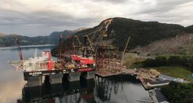
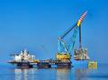
The size of the hull, at 198m-tall, has been driven by project requirements–the 1300m water depth, harsh environment, and need for condensate storage.
In turn, the scale has driven further firsts. Supplier Vulcan SFM, a subsidiary of Sheffield Forgemasters International, believes the four cast deck connection nodes it is providing to connect the deck to the hull will be the largest cast nodal joints manufactured to date. Vulcan believes it will also be the first time cast nodes have been used within a spar truss hull.
The largest offshore cast nodes previously supplied by Vulcan were two 110-tonne trunnion nodes, used for lifting Statoil’s 9000-tonne Valemon jacket into place in the Norwegian sector of the North Sea, in 2012 (OE: August 2012). They measured 4.6x4.4x3.7m.
“That record was soon broken by the truss nodes (also known as leg nodes or heave plate nodes) in the hull for Aasta Hansteen, weighing 117-tonne and measuring 4.6 x 4.6 x 4.6m,” Mockford says. “But that was then also broken when we also won the contract to supply the deck nodes (at 120-tonne each).”
 |
| The Aasta Hansteen spar, illustration. (Statoil) |
In total, Vulcan SFM is providing 36 castings for the Aasta Hansteen spar, from relatively small pull-tube castings, to the ultra-large truss and deck nodes, which it has designed.
The spar
The Aasta Hansteen spar is formed from two main segments, a truss spar hull, and 23200-tonne topside. The topside will rest on the top of the hull via four deck leg supports, and four deck nodes.
The hull section will comprise of a truss connected to the hard tank at the top and the soft tank at the bottom. The main leg and brace tubulars will be connected by eight truss nodes of varying sizes, which also connect to the heave plates. Four nodes connect the legs to the hard tank. Rigid steel catenary riser pipes will run through the truss hull section down to the sea bed, more than 1300m below the platform.
Deck nodes and deck leg supports
The 140-tonne deck leg supports, fabricated from two cast cone sections, are the uppermost component of the hull’s union with the topside. They will be spaced 27m apart, from center line to center line, on top of the hull. The most highly-loaded deck leg support has been designed for a maximum vertical, factored design load of 19,300-tonne.
The 120-tonne deck nodes, which will have shaped stubs, onto which the horizontal I-beams will be welded, and connection points for the tubular columns, will form an integral part of the topsides’ super-structure. Once completed, the topside will be transported from Hyundai Heavy Industries’ yard in South Korea to Norway, and the deck nodes will be mated with the deck leg supports on the hull in a Norwegian fjord.
 |
| A truss node pattern in construction (Vulcan SFM) |
After initially designing fabricated deck leg supports with cast ring flanges, discussions with supplier Vulcan SFM led contracted hull-designer Technip to opt for a fully-cast flange and cone.
Due to manufacturing and logistical constraints, including road bridge heights, each deck leg support will be created from two cone-shaped castings, with the lower piece coming complete with a 5.9m-diameter flange ring (the flange is usually cast, with the rest of the node rolled plate).
To design the nodes, Vulcan uses critical load data gathered from the client. The data is ran through stress-strain analysis, which allows Vulcan to create a high-quality casting by controlling how the steel flows through the mold, and how it will cool and solidify.
Once cast, the separate deck leg support pieces will transported through the port of Goole, England, and probably Antwerp, Belgium, to Korea, where they will be welded together and integrated onto the hull. To give an idea of scale, the flange rings for previous spars cast by Vulcan have weighed about 7-tonne. On Aasta Hansteen, the equivalent section (ring flange only) would weigh nearly 50-tonne.
Ultra-large truss nodes
The ultra-large truss nodes are more complex to cast. These weigh 70-117-tonne, depending on where they are in the spar truss hull. The largest would occupy a 4.6m-wide cube. They form high-strength and fatigue-resistant nodal joints to connect the main leg and brace tubulars in the truss section of the spar platform. They also connect to the heave plates and the hard tank.
 |
| A completed mold section (Vulcan SFM) |
“The truss nodes are difficult castings because of their sheer size and complex geometry,” Mockford says. “Up to eight brace stubs connect onto the leg can. It is very important to optimize the method of casting in order to ensure a high quality of casting. The casting method is verified by computer simulation of the flow and solidification of the steel within the casting. This gives us the ability to get each casting right first time.”
Casting
The first truss node was cast at the end of June 2013, and the first four truss nodes will have been completed by press date. The production timescale for a typical large node such as the truss nodes and deck nodes is about eight months, Mockford says. This comprises of: 10 weeks for design and pattern making; 24 weeks for production. Further castings are produced concurrently and completed.
Production time would typically involve: four weeks for core and moldmaking; one day for casting; three weeks for cooling; one week burning off the risers and feeder heads; two weeks for an initial heat treatment (normalize, quench and temper); seven weeks for surfance clearning, or fettling, NDT, and weld repair; five weeks for machining; three days for a final heat treatment; and one week for final inspection and release.
Once a cast component is designed, a mold has to be created. First, craftsmen build a pattern, replicating the external profile of the casting, from wood, taking into account the shrinkage of steel as it cools to create the precise finished size. For the larger truss nodes, 19 separate pattern pieces had to be produced.
A mix of black sand and resin is then packed around the pattern pieces, which are contained in large boxes. The sand and resin is then allowed to dry hard, to create components, which will make up the full mold.
 |
| The mold being assembled in the pit. (Vulcan SFM) |
The mold components are then assembled into a 5.5m-deep pit, forming the complete mold.
Fascia coming into contact with the liquid steel are coated to prevent any sand breaking loose and to allow for clean separation of the casting from the mold.
Steel-making, which involves heating the steel up to 1700°C, is carried out on site. Liquid steel is then transferred to the mold pit in 90-tonne ladles. Multiple ladle pouring needs to happen at the same time, which means each ladle needs to be heated to a specific temperature so that they are about 1560°C when ready for pouring.
A high-strength steel, CSN 400, has been developed specifically for offshore structural castings. It is compatible with the steel plate used in offshore structures and is readily weldable.
Liquid steel must steadily flow into the mold from below to avoid potential surges created by the pouring process. Once the casting has cooled, the mold is broken away. To cast the same component again, additional molds would need to be created from the original pattern.
Quenching, tempering and fettling
While the pouring takes just minutes, the cooling process can take several weeks, after which the cast piece has to go through a series of treatments. First, the feeder head and risers, which allow the steel to flow in to the mold, are cut away. The feeder head takes an overflow of liquid steel to “feed” the casting as it shrinks during cooling, so no voids form.
Next, the casting is normalized, quenched, and tempered. During the quenching process, the casting is heated in controlled stages up to 900°C, held for several hours at this temperature, and then water-quenched.
 |
| Three ladies pour the liquid steel into the mold. (Vulcan SFM) |
Vulcan’s quench tank is 7.4m-wide, 5m-deep, and holds 79,000 gallons of water. During quenching the tank is agitated using impellors and water injection.
This increases the strength of the casting. However, it also makes it more brittle. To improve the casting’s ductility, it is then tempered-heated to 580°C and then allowed to air cool.
Fettling – a refined cleaning up process – non-destructive testing (NDT), weldrepairs, and machining are then performed, before the final stress-relieving heat treatment, at 560°C, and air-cooling.
Vulcan worked closely with Technip on the design of the hull castings, and with CB&I, the topside designer and manager, to design the deck node castings.
All castings for the project are due to be complete by the end of May.
 Subscribe