Houston-based Helix ESG recently completed a deepwater well decommissioning project in 7919ft. Darin Hilton explains the steps and options involved in plugging and abandonment.
 Over the past several years, there has been a growing demand in the industry to safely and efficiently plug and abandon wells in the Gulf of Mexico (GOM). Having successfully decommissioned over 30 wells in more than 3,500ft water depth in the GOM, Helix ESG has enabled clients to achieve a more efficient, safe, and cost-effective method of securely and permanently abandoning deepwater subsea oil and gas wells to meet regulatory and industry standards for several years.
The key elements to Helix’s success is purpose-built vessels with a dedicated Intervention riser package and experienced crew and project management teams to support the client in planning the job.
THE Q4000 AND PURPOSE-BUILT VESSELS
The Q4000 has been the main vessel utilized by Helix for riser-based GOM plug and abandonment (P&A) work for the past decade, with one reason being that the open decks and large cranes provide efficient mobilization of client equipment. Another advantage to the Q4000 is that The open multi-purpose tower (MPT) on the Q4000 allows unrestricted access on three sides, allowing for easier change of operational modes from, electric line, slick line, or coil tubing. In most cases, with a purpose-built vessel and a dedicated intervention riser system (IRS), stack-up and surface image testing (SIT) can be completed in transit, reducing the amount of testing time on critical path. Once mobilization and testing is complete, the vessel runs the multiplex (MUX) controlled intervention riser system to depth, utilizing a dual-string riser. The intervention riser system is unique and is comprised of a lower riser package (LRP) with a 7 3/8-in. production through bore. The LRP also provides cut and seal fail-safe barriers on both the annulus and production sides.
The IRS system is also equipped with a emergency disconnect package (EDP) to quickly detach and seal in the event of an emergency or station keeping incident. The EDP itself is equipped with a valve to ensure riser fluids are retained within the pressurized riser should the emergency disconnect sequence be required. The IRS system is a lighter package than a traditional blowout preventer (BOP), minimizing stress on the supporting well tree during latching.
Managing down lines, MUX cables, and a separate annulus line while operating an IRS requires proper set-up and an experienced crew. The riser also should be pressure-tested periodically to confirm riser integrity while running.
ACCESSING THE WELL WITH THE IRS PACKAGE
Once the IRS package is ran to depth in an identified safe zone, riser space out is confirmed by moving the IRS package over the well. The surface system is then rigged up with flow head, coil tubing lift frame and coil tubing BOPs once it returns to the safe zone. The system is then landed and latched up on the well utilizing passive and active heave compensation. ROVs will then connect the installation workover control systems (IWOCS) and electric down line (EDL), utilizing hydraulic flying leads (HFL) and electronic flying leads (EFL) jumpers for tree control. The IRS will then be pressure-tested to confirm integrity and the riser will be displaced with working fluid prior to opening the well.
WORKING DOWNHOLE
 Downhole work begins once well access capability is established. If the well is designed with a horizontal tree, the first run will be for slick line to pull crown plugs. Coiled tubing is usually a contingency to slick line in case of stuck crown plugs or embedded debris. The IRS and riser can usually increase pressure on the bottom of the crown plugs to assist with retrieval. Once the well is opened, tubing fluids are displaced and the production zone is then killed with kill weight fluid. Another option is to run a tubing punch on electric line to create a flow path above the production packer, allowing for packer fluid in the annulus to be bull headed into the formation rather than circulating it out to surface. Either option is achievable in most cases. Once the well is killed, a gauge ring ran on slick line is conducted to ensure vertical access in the production tubing. Coiled tubing is then rigged up and ran to bottom. Coiled tubing ensures the plug is correctly located, provides an additional means of circulation if problems are encountered, and protects the tree and well control equipment from exposure to cement.
After the cement is cured, the production plug is tested to confirm integrity. Once the pressure test is satisfactory, the first of two balanced cement plugs is set, sealing both the production tubing and annulus above the production packer by taking returns though annulus. Coiled tubing would then be recovered and electric line prepared. Once the cement is pressure-tested and its integrity with the balanced plug is confirmed, an electric line could then be ran into the well to act as a mechanical barrier in the production tubing above the cement plug. Electric line then perforates the tubing to prepare for the second balanced plug to be circulated into place with coil tubing.
Once the second balanced cement plug is set and successfully pressure tested, electric line is directed into the well with a tubing cutter. The production tubing would be cut above the balanced plug to allow for the recovery of production tubing. Prior to unlatching, a negative test is performed with sea water and then well circulated to ensure kill weight fluid on both production and annulus sides in the well.
OPEN WATER AND SETTING THE PLUG
 Prior to pulling the trees during the riser-based portion of the P&A, ROVs flush and remove any flow line jumpers by pre-rigging them with slings and cutting the jumper into manageable sections for the subsea crane to recover concurrently to the P&A work. This eliminates the need for a construction ROV vessel to perform any pre-work prior to arrival on location of the P&A vessel.
Once tubing is clear of the well the vessel will move to a safe zone to finish recovery. If the well was designed with a vertical tree, the IRS would be recovered through the riser and the tree would be concurrently recovered by the subsea crane. A tubing hanger running tool would then be tripped to bottom on drill pipe to retrieve the tubing after the IRS was recovered.
The open water-portion of the P&A can been done in many different ways, with different approaches to testing casing annuli. The most common method is utilizing the easy drill subsurface valve (EZSV) and a tubing-conveyed perforated (TCP) gun to allow access to the annuli. This method is performed by tripping the EZSV and TCP guns to depth and setting the EZSV. Once EZSV is pressure tested from below to confirm it was properly set, the TCP guns will be fired, perforating the production casing. Pressure is monitored and recorded during firing. Any existing pressure will be bled off and monitored again.
 An injection test is then conducted at a pressure greater than leak-off test pressure to check the integrity of the annulus. If injection is possible, a squeeze-cement job will be performed on the annulus. If injection is impossible, then a negative test is performed to confirm integrity. The string is then retrieved from the retainer. Once integrity of the squeeze is confirmed by both the pressure test and the negative test, a cement plug is set above the EZSV. The process would be repeated for the intermediate casing to 20in annuli perforating through two sets of casing with TCP guns.
Another option is to cut the production casing and recover to surface once annulus integrity is confirmed between production and intermediate casing, allowing for a mechanical barrier to be set in the intermediate casing. If this option is elected to be performed, the TCP gun would only be required to perforate the intermediate casing to ensure integrity rather than perforating two sets of casing to access the intermediate to 20-in. annuli. Once complete, a surface plug would be set. The surface plug is weight tested, utilizing drill pipe to tag the top of the plug and set down weight to confirm the plug has integrity.
Upon completion of the surface cement plug, an ROV will set a debris cap on the wellhead, completing the well work. The vessel will then perform a final survey with the ROV and complete demobilization from the well site. OE Review
 Darin Hilton has been Helix’s commercial manager for Well Operations in the US since 2012, and has worked for Helix Energy Solutions Group for more than five years. He has more than 18 years of experience in the offshore industry. Early in his career, Darin worked at Marine Transport Lines. Darin also worked at BP as a marine supervisor with and a superintendent for three producing fields.
At Helix, he has served in three roles, including a three-year stint as Master/ OIM on the Q4000 during the oil spill response at Macondo. Darin holds a BS in Nautical Science with a minor in Marine Engineering from Maine Maritime Academy. Darin also has a USCG Master Unlimited Tonnage license with OIM-unrestricted endorsement.
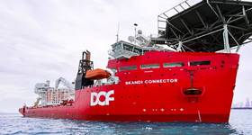
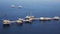
Image Caption (top): The Q4000, Helix’s vessel of choice in riser-based GOM work for the past decade.
Photo: Helix ESG
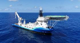
Image Caption (2nd from top); A crane atop the Q4000 rigging up coiled tubing to perform deepwater P&A work.
Photo: Helix ESG
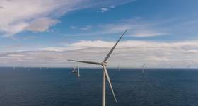
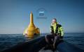
Image Caption (3rd from top): An ROV engaged in operations.
Photo: Helix ESG
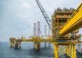
Image Caption (bottom): Open decks and sizable cranes aboard the vessel provide more efficient mobilization.
Photo: Helix ESG
 Subscribe