Satnam Shoker, of Step Change Engineering, details a new automated, streamlined process, which helps save time during brownfield modification work.
 |
|
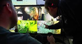
Scan data of cooler inlet pipework imported directly into Autodesk Recap. Image from Step Change Engineering. |
In a mature basin, such as the North Sea, brownfield modifications work on facilities designed up to 40 years ago, but need to continue producing, can be a challenge.
Access to pipework, bed space for inspection personnel, logistics, etc., all add up and can challenge project economics.
What if you could streamline all that work, remove the need for specialist inspection personnel, and use design data auto-generated from handheld infrared (IR) scans, which can then also be quickly converted into engineering drawings for fabricators?
Aberdeen-based Step Change Engineering is doing just this. The firm has developed an automated, streamlined process for like-for-like and small- to medium-sized modifications. Its workflow covers all stages of a project scope, from work initiation, technical appraisal, conceptual study and detailed design through to procurement, delivery of materials, offshore construction support and closeout.
 |
|
Screen shot from Navisworks Simulate. Using Navisworks Simulate SCE can save an AutoCAD model to a format that can be read by Navisworks Freedom which is a free 3D viewer. Image from Step Change Engineering. |
The system is based on three elements: offshore data capture, using handheld IR scanners; 3D modeling and design work (using the IR data); and then automated deliverables output – i.e. engineering drawings are generated automatically, directly from the design applications, using the firm’s software.
This can include various structural and piping design deliverables, including piping isometrics/general arrangements (GAs), perspective GAs, line list, structural GAs, fabrication drawings, bill of materials/material take off (MTO), and a construction worksheet.
For simple scopes, the entire work pack can be produced onto a single A3 construction worksheet containing the MTO, job cards, resource requirements and construction activities. Detailed workflows can also be created in the system, such as client and contractor responsibilities, which can be tailored to suit a client’s requirements and procedures.
Using client-owned handheld scanners, on which staff can be easily trained, immediate savings on time and cost can be made, with rope access technicians able to use the devices in hard to get at areas – avoiding the need for scaffolding.
For minor modifications and spools we have confidence in the manufacturer’s quoted figure of 0.5% accuracy. Flange offsets and bolt-hole orientation would be measured by traditional methods. Caution should be exercised where less than +/- 1mm accuracy is needed.
Step Change Engineering has been applying this technology in the UK North Sea on several platforms and floating production systems, covering multidiscipline and single discipline modification scopes at concept and front-end engineering and design stages.
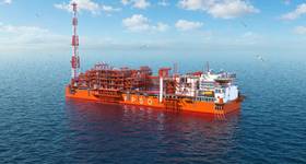
Brent Alpha
One such project, for oil major Shell, on the Brent Alpha platform in the UK North Sea, enabled 70% cost savings, using Step Change Engineering’s method, compared to a conventional scope.
 |
|
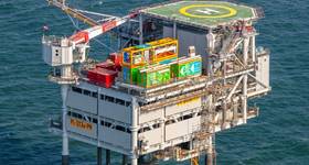
Brent Alpha in 1977. Photo from Shell. |
During early 2015, Step Change Engineering approached Shell with a solution for brownfield modifications, including like-for-like pipework and structural steel replacement, often referred to as repair orders (ROs) or material and corrosion defect reports (MCDRs).
Initially, there was a degree of caution and a series of practical demonstrations and testing were done to prove the technology, including its accuracy and suitability for offshore use.
Following successful trials, Shell issued Step Change Engineering with a contract in July 2015 to design and fabricate an existing MCDR scope.
The initial MCDR selected by Shell was to replace an approximately 6m length of a corroded section of pipework in the 6in exhaust line of a diesel engine on one of the Brent Alpha fire pumps. One of the challenges with this scope was that the exhaust pipework was difficult to access and high-up.
Traditional approach
Conventionally, the inaccessibility of the pipework would have required a large scaffold platform to be erected to allow safe access, initially for a piping designer to perform a detailed design survey, and then for the offshore construction team to carry out the necessary destruct/construct scope required to replace the corroded pipework spools.
For this job, which was typical of many brownfield repair/replacement type scopes, such offshore scope elements extend the project schedule and add significant extra cost, particularly in relation to the onshore design and fabrication requirements, which often are a relatively small proportion of the overall cost.
 |
|
Single sheet work pack. Image from Step Change Engineering. |
Our approach
Step Change Engineering’s workflow allowed an alternative solution to be proposed, i.e. deploying rope access technicians to perform both the design survey and the construction scope. This addressed the main cost/schedule issues by avoiding the requirement for scaffolding and eliminating the need to use a piping designer to perform the survey.
Survey data was captured in less than 30 minutes using a portable hand-held scanner by Shell’s rope access technicians, who were trained to use the scanner beforehand and are part of platform’s core construction team. The scanned data was emailed to our onshore design team where it was imported into our 3D modeling and design applications suite.
Once the pipework was modeled, further cost and schedule efficiencies were achieved by auto-generating a range of deliverables directly from the model. This took less than four hours, including checking.
For this first MCDR scope, Shell incurred a one-off cost for training the rope access technicians, which Step Change Engineering carried out at its premises. Shell had already purchased a hand-held scanner for use on the Brent platforms and Step Change Engineering simply updated the software and tested the unit to ensure it would be compatible.
Key benefits
The rapid data capture and auto-generated deliverables resulted in a significantly reduced project schedule. Piping isometric drawings were auto-generated with detailed fabrication information including the necessary piping cut lengths and weld preparation details, which avoided the need for the fabricator to mark-up the drawings (as would be the case traditionally) and further helped to reduce overall delivery time.
Overall, the data capture, design and fabrication scope was completed with materials delivered within approximately 1-2 weeks, compared to an estimated 4-8 weeks doing it the traditional way.
Cost savings exceeded 70% when considering the requirements for scaffolding and dedicated design survey were eliminated from the scope.
Another recent project for Shell included the development of a conceptual design for installing a temporary pig launcher. The study was completed within one week, including the survey time, compared to 4-8 weeks conventionally. Deliverables included a 3D CAD model, construct/destruct piping and instrumentation diagrams, destruct isometrics and a perspective GA with a detailed bill of materials.
Satnam Shoker is consultancy director at Step Change Engineering. He has spent more than 27 years working in the oil and gas industry and is a Fellow of the Institution of Chemical Engineers.
 Subscribe