The pressure is on to find economically viable ways to develop marginal fields, in the UK North Sea and further afield. Ben Smith and Ed Randall look at the challenges and options.
More and more emphasis is being placed by operators and governments on exploiting reserves that have previously been deemed uneconomic – in other words, marginal oil fields.
Often conventional solutions prove too costly or unsuitable for marginal fields, so more novel and innovative designs require due consideration. Atkins has developed extensive experience in developing such designs.
 |
|
Articulated tower concept. Images from Atkins. |
What are marginal fields?
Marginal fields typically share one or more of the following characteristics that can result in high risk to returns on capital investment, heightened sensitivity to oil price, or escalation in Capex and Opex during field development:
 |
|
Articulated tower concept. |
Where these factors apply, it is often more practical to ask the question “given an assumed production profile, oil price, Opex and Net Present Value for the estimated reserves, what is the maximum Capex that still ensures an attractive return on investment?”
Characteristic solutions
In performing concept engineering and selection, there are a number of guiding questions that we have found useful:
 |
|
Articulated tower concept. |
On the UK Continental Shelf (UKCS) alone there are a number of innovative options specifically designed for small fields that attempt to answer these questions. These include operating assets, such as the Sevan 300s, operating on the Chestnut and Huntingdon fields, and those in planning including Arup’s ACE Platform, destined for the Bentley oil field, and a range of production buoys (OE: May 2014).
The following examples demonstrate how some of the above questions have been answered across a number of projects carried out in Atkins. A key theme running through these examples is that of combining a relatively old idea – oil-over-water storage – with modern approaches to managing safety and potential environmental impact.
Stranded fields and subsea tanks
For remote fields where the reserves cannot justify the cost of installing a pipeline, subsea tanks are often a viable alternative to a floating storage and offloading unit. The technology is mature with multiple examples where it has been successfully employed. In a previous study for a UKCS marginal field, by careful iteration between process and structural design, Atkins devised a low-weight facility that minimized overall Capex by combining a subsea tank and an articulated tower to support a normally unmanned installation.
The compliant tower is tuned to avoid environmental loading, as opposed to the use of rigid restraint provided by conventional fixed structures. The steady wind and current loads are resisted by the floating stability of the column – which has its center of buoyancy below its center of gravity, achieved by using solid ballast.
The concept was deemed sufficiently robust by investors to allow further drilling in the area resulting in an increase in proven reserves allowing a more complex facility with higher topsides weight to be justified utilising a conventional jacket. The tank was retained and progressed through to detail design by Atkins.
One particularly innovative feature of this subsea tank is that it is not open to the sea (free venting) but has a “closed loop” connecting both the sea-water and oil portion of the tank with the topsides production facility. This removes the need for subsea pumps, reducing complexity and environmental risk.
Reusable, floating production systems
 |
|
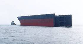
FPS3 Hull. |
Various forms of floating production systems satisfy the fundamental requirement for re-usability, and lower initial Capex (through lease/charter arrangements), becoming a “go-to” solution for marginal fields. However, not all traditional FPSOs are necessarily suitable for marginal fields for various reasons including:
The need for more small, low Capex solutions, particularly for harsh environments, suggest a further “sharpening of pencils” is needed – the following two examples illustrate how this could be achieved. Both use of oil-over-water storage, to reduce hull steel-weight and cost, capturing the benefits of the subsea-tank, but providing mobility and re-usability.
A semisubmersible solution – FPS3
In extreme environmental conditions a semisubmersible hull form offers clear benefits. To suit a UKCS field, Atkins developed a production and storage semisubmersible termed the FPS3. The design drivers included the need for a large and flexible deck space and payload, low Capex (of order US$250-400 million), safe access for inspection and provision against environmental impact.
The deep draught hull tunes its motions away from the local peak wave period giving it excellent motion characteristics for a northern North Sea or West of Shetland environment.
 |
|
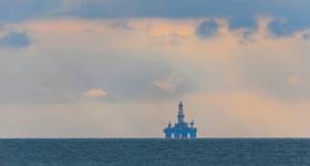
FPS3 structure. |
The choice of oil-over-water storage reduces segregated ballast water requirements significantly. The cargo tanks remain pressed full of liquid (oil/sea-water) at all times, such that there is no free-surface effect to reduce reserve of stability; no vapor spaces that might lead to enhanced explosion risk, and minimal movement of the cargo KG throughout the operational cycle. This arrangement reduces steel-weight and substructure fabrication costs significantly.
The FPS3 was configured for up to 300,000 bbl storage, which allowed it to be used either:
a) As a pure marginal field solution in harsh environments (production rates of up to 25,000 bo/d)
b) To develop larger fields with higher initial production (e.g. 50,000 bo/d) producing into an attending shuttle tanker, with the storage capacity as “buffer” whilst the attending tanker is off station to unload. As oil production rates drop later in life the smaller Opex facility is better matched to the size of the field.
 |
|
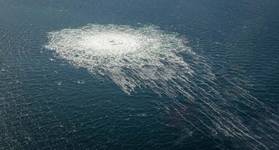
A compact-FPSO (C-FPSO) design. |
A compact-FPSO (C-FPSO) design
The FPS3 demonstrated that there is room for further innovation in FPSO design for marginal fields. Can we develop an even lower cost solution for yet more marginal fields that might be constructed and installed for no more than $250 million?
In two studies for North Sea fields with an estimated life of 7-10 years, Atkins developed a small deep-draft buoy with a single central oil-over-water cargo storage tank combined with a conventional integrated topsides. This innovative concept serves as a low Capex – low Opex solution and provides processing and offloading facilities on the smallest platform “footprint” affordable. The key features of this patented concept (GB2507370) are outlined below.
The C-FPSO’s deep draught near symmetric hull form gives beneficial motions characteristics similar to those of a SPAR. Heave plates also give the concept inherently high natural periods. The motion is relatively insensitive to wave direction which allows the unit to be spread moored thus removing the need for the turret and swivel found on conventional weathervaning FPSOs.
For a conventional offshore structure such as a semisubmersible, or ship-shaped unit, wave loads typically govern the structural design and often limit the operational fatigue life due to global loading. For the C-FPSO, the global wave loads are at a minimum and the internal arrangement is set out to focus on load carrying horizontal hydrostatic pressure. For this reason the structural design of the hull is surprisingly simple. By making use of a conventional stiffened plate structure and simple symmetric repetitive design; the overall construction risk and engineering timescales from concept design to unit delivery are minimized.
The C-FPSO has been designed to accommodate a conventional integrated topsides payload in the range of 4500 to 6500-tonne – depending on storage capacity. The integrated topsides allows this design to maintain a distinct separation between the production fluids process systems, power generation and accommodation, and the hull systems, including cargo storage and offloading. This simplifies construction and installation and gives flexibility in re-use of the facility.
During production, the cargo is fed into the top of the single oil-over-water cargo tank, and displaces water removed from the bottom via a central caisson, treated and discharged overboard. Only small compensating ballast tanks are required to maintain draft and meet damage stability requirements. At offload, cargo pumps on the topsides deck transfer the crude via an offload reel on the weather deck to a shuttle tanker while sea water is pumped into the cargo tank from below.
Risers are routed via a hang off frame located on a cellar deck of the topsides. All hazardous process equipment is kept in open and freely ventilated space, and provides good, multiple access to emergency escape routes, even on this very small facility. Minimal marine facilities reduce persons on board requirements significantly.
 |
|
Heave response and wave period charted. |
Conclusion
It is becoming increasingly important to look for means to exploit economically marginal fields that may be remote, have short production life, extreme environmental conditions or flow assurance difficulties. The “closed-loop” oil-over-water approach has helped develop some particularly cost-effective approaches to exploiting stranded and marginal fields, safely and environmentally. It is clear that in order to continue to drive down Capex, particularly in an era of uncertain oil price, much smarter engineering combined with better ways to manage technical and economic risk is required.

Ben Smith is a naval architect within the Oil and Gas business at Atkins based in London. He joined Atkins in 2010 principally focused on the design of assets for marginal fields. He graduated with an MEng from the University of Southampton.

Ed Randall is a chartered naval architect with a focus on early stage design where maximum value can be added. He has project managed multi-disciplinary concept, FEED and detail design projects and leads the floating systems team in London. Randall holds an MSc in Naval Architecture from the University of Southampton.
 Subscribe