.jpg) |
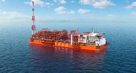
| CSP (conductor supported platform) topsided being loaded into the Industrial Force vessel at Sfax, Tunisia, for transportation to Cotonou, Republic of Benin. Photos from Aquaterra. |
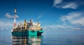
After being abandoned in 1998, the Republic of Benin’s only oil field is due to resume production, using a minimal facilities conductor supported platform design. Elaine Maslin reports.
Benin has a 171km-long coastline, which runs along the Gulf ofvGuinea between Nigeria to the east and Togo to the west.
The country’s main offshore sedimentary area consists about 3500sq km on the continental shelf (up to 200m water depth) and 8000sq km in deep water (200-3000m).*
But, to date, the country has produced just one oil field, Sèmè, and it has been shut-in since 1998. Now, Sèmè is being brought back to life, with the help of a conductor supported platform (CSP).
The Sèmè field was discovered in 1968, it sits at 40m water depth, 15-20km offshore. First production was in 1982, via three platforms, and, after 1988, two monopod towers were added. However, operations at the field ceased in 1998 (A Historical Dictionary of Benin by Mathurin C. Houngnikpo and Samuel Decalo, 2013).
Post-1998, Nigeria-based South Atlantic Petroleum (SAPETRO) took over a 100% interest and operatorship in Block 1, containing Sèmè, under a production sharing contract with Benin’s government. SAPETRO says Sèmè had produced more than 20MMbbl up to 1998.
The company says it acquired 350sq km seismic data over the acreage in 2007, and by the end of 1Q 2009, SAPETRO had drilled two appraisal wells; Central Sèmè West 1 (CSW-1) and the Central Sèmè East (CSE), in the central part of the Sèmè structure, to confirm the existence of by-passed oil.
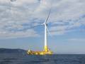
SAPETRO had been considering a standard jacket design, but brought in UK-based Aquaterra Energy, which offered a design based on its unique minimum facilities Sea Swift CSP design, a solution created for marginal fields in shallow, benign waters, and able to be installed using conventional drilling and handling techniques from a jackup drilling rig, without the need for additional heavy lift vessels.
Sea Swift
The general Sea Swift CSP design concept is a topside structure, to house wellheads and Christmas trees, supported on conductors, which are braced by a subsea structure, into which the conductors are drilled, cemented, and grouted, to provide structural support and stiffening.
“The primary driver for using a CSP is to make marginal fields economically viable by providing a minimum facilities platform on which dry trees are installed,” says Richard Miller, operationsdirector, Aquaterra Energy. “The CSP concept is that a jackup drilling rig can drill the wells while also installing the CSP subsea structure and topsides using its top drive and heavy lift package.”
The Sea Swift design is a scalable system to meet each specific application, he says.
“One of the primary drivers of the CSP design solution is what rig is contracted to drill the wells—the operational capacity of the jackup drill rig. Bathymetry, metocean and soils data are also important considerations, defining the design.”
Miller says a CSP could be used in up to 80m water depth, depending on such factors, and Aquaterra Energy has already designed and installed a Sea Swift CSP in 65m with a 450-tonne topside.
A key part of the design is using NOV’s XLCS high-fatigue resistant conductor connectors, which enable conductors to be run and installed to the required depth, using standard techniques employed on a traditional jackup, while providing the necessary structural integrity needed.
.jpg) |
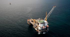
| Subsea structure ready for installation using the Noble Tommy Craighead jacku drilling rig. |
Aquaterra Energy’s Sea Swift CSP design was first used offshore West Africa in 2007—two Sea Swift CSPs, Solha and Airoga, were installed offshore Angola.
A third CSP was installed for Petronas offshore Malaysia last year. This installation was in 65m water depth. Its topsides, comprising four decks (weather, mezzanine, main and lower), has an operating weight of circa 450-tonne, sitting on four, 36in. by 2in. thick wall, structural conductors, with five internal conductors. It had two, 300-tonne, subsea structures and the CSP catered for 16 oil production wells, 11 with gas lift and 12 water injection wells, connected to an 8in. export riser.
The Malaysian CSP was a wellhead support structure and was operated in conjunction with a mobile oil production unit (MOPU), which housed the water injection and downstream production facilities and electrical power generation, Miller says.
Sèmè
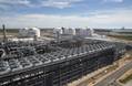
The Sèmè CSP will be used to flow up to five wells, in 26m water depth, to an onshore processing facility 15km away. The CSP consists of a 220-tonne integrated topside, riser guides, boat landing, and a 121-tonne subsea structure. Its topsides and subsea structure were built by Tunisian fabricator, Socomenin, at their Sfax facility, under supervision by Aquaterra Energy. Production will be controlled from an onshore facility at Cotonou, Benin’s largest city, via an integrated fibre optic communication and power cable.
The topside structure comprises cellar and production decks, including a large control room, which houses transformers, to step down the incoming 11Kv power supply used by the electrical submersible pumps deployed into the wells, controlled via variable speed drives, and motor control centre.
The wellheads and Christmas trees will be accommodated on the production deck and four, structural, 30in., 1½in. wall thickness, conductors support the topsides, while also housing the well casings. Riser guides, providing support and protection to the export riser, power cable and sea water caisson, are run and supported from two conductors.
While the Sèmè CSP sits at 26m water depth, with a 12m air gap, the design had to take into consideration softer soil conditions than on the Malaysian CSP. On location at Benin, it is not until 15-20m deep that stiff clays are found to provide support, requiring 80m of conductor to be installed below the mudline, despite the shallow water depth.
.jpg) The subsea structure comprises four leg cans and cross members, bracing the four structural conductors, and increasing the fatigue lives of the conductors caused by the environmental loading effects caused by wave action on the risers.
The subsea structure comprises four leg cans and cross members, bracing the four structural conductors, and increasing the fatigue lives of the conductors caused by the environmental loading effects caused by wave action on the risers.
The topside process piping includes a pig launcher and multiphase flow meter complete with test facility for each well, and a common manifold, which takes the un-processed three-phase crude off the platform to shore via the 8in. pipeline. Access for personnel is via boat, using a boat landing platform, and a secure entrance hatch. CCTV systems, looking inward and outward, have been installed, and the platform is fitted with navigation aids.
While the CSP topside would normally be installed by the jackup completing the drilling operations, an available pipelay vessel was used for the Sèmè field topside installation.
“As the project had the opportunity to utilise the infield pipelay barge, the topsides was installed by the barge; this in turn reduced the lift weight constraint caused by the jackup lift and skidding capacity required for the installation,” Miller says.
“The subsea structure was installed by the rig (the Noble Tommy Craighead).” Installation of the Sea Swift CSP on Sèmè started at the end of March, with installation completed by the end of April.
* Project Completion Report, Benin. Petroleum sector technical assistance project. February 1990, World Bank.)
 Subscribe