With floating LNG facilities now widely acknowledged to be a key enabler for exploiting stranded gas reserves, Trelleborg Marine Systems' Simon Wilson offers some insights into the new design methodologies needed for integrated berthing and mooring specifically for LNG handling in a dynamic offshore environment.
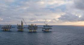
2010 heralded wide industry acceptance of offshore LNG concepts and technologies with several projects nearing completion and many new concepts receiving support to proceed during the next 12 months. We have now seen a full year of operations of the first LNG floating storage and regasification unit (FSRU) and the installation of a second FSRU vessel in Dubai. Floating LNG (FLNG) is now generally recognised as the most viable, cost effective solution to exploiting remote or stranded gas reserves.
The most challenging of the offshore LNG projects are FLNG liquefaction vessels; the first of which is due for completion this year. FLNG vessels, in barge or ship shape hull form, will provide floating terminals that extract and liquefy the gas, store the product and transfer it to an LNG carrier. Floating LNG liquefaction vessels will potentially enable hundreds of presently unviable gas fields to be exploited over coming decades.
While the systems used for berthing, mooring and mooring management at onshore LNG terminals may be considered directly suitable for FLNG applications, in a highly dynamic marine environment this assumption may lead to high risk situations.
Although the basic elements may be similar, an understanding of the demands of an offshore environment is key to successful system development.
Through unravelling the complexities of FLNG berthing and mooring, and highlighting the differences, an insight is gained into the new design methodologies needed for integrated berthing and mooring specifically for LNG handling offshore.
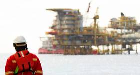
Safety and risk management
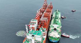
FLNG ship-to-ship operation requires the LNG carrier, or secondary vessel, to be berthed with about 5m separation from the FSRU, or primary vessel. Close berthing is required for the hard LNG loading arms that will be used on many of the current projects.
The approach and berthing of the secondary vessel, reliably deploying the fenders from the primary vessel and transferring and managing the moorings are vitally important. Each action must be performed faultlessly to maximize the window of opportunity for loading and to minimize the time the vessels spend sideby- side.
The safety and risk management demands of the LNG industry require the best technology and tools. Overlying are commercial pressures; any interruption or delay will be costly. Reliable and effective systems for berthing, fender handling, mooring and mooring management are mission-critical.
A ‘standard kit' has evolved for most modern onshore LNG facilities. The common elements include, firstly, a fixed fender system for protecting the facility. By keeping the berthing forces to acceptable levels, this minimizes berthing hull pressure and offers a low-friction fender interface to protect the berthing vessel's hull and coating system.
The quick release mooring systems comprise quick release hooks for head, stern and spring lines, incorporating integrated mooring line tension monitoring and remote release systems.
Docking aid systems installed onto the jetty are widely used to assist the pilot in berthing the vessel. They also record key elements of the berthing process such as vessel speed, distance to fender and angle of approach. Docking systems are complemented by environmental sensors to provide wind, wave and current monitoring.
The majority of modern terminals have an integrated marine monitoring system that provides a central system of alarms and information important to operations. This interfaces with the fibre-optic shipto- shore communications and loading shutdown systems, a portable carry-onboard workstation (for LNG carrier), and the plant distributed control system to provide the berthing and mooring feedback to marine operators both on the jetty and LNG carrier.
FLNG transfer technology currently relies on a ship-to-ship mooring configuration to allow offshore versions of loading arms to manage the transfer. In this configuration the logical solution would be to utilize the integrated marine monitoring system concept for FLNG applications.
But can the equivalent onshore 'standard kit' simply be bolted to an FLNG and offer equivalent benefits?
To answer this we need to look at the similarities, and differences, between the two types of operations with respect to berthing and mooring, plus some distinguishing requirements unique to FLNG.
Mooring
Similar to onshore mooring, ship-to-ship FLNG will have between 10 and 20 sets of mooring hooks, capacity 100-50t SWL, configured as double and triple hooks. In addition, FLNG requires systems to be designed and manufactured in accordance with class rules such as DNV, Lloyds, RINA and ABS, which require compliance with applicable mechanical, structural and electrical design rules.
The recommendations carried in the recent Oil Companies International Marine Forum Mooring Equipment Guidelines 3rd Edition (MEG3) are also relevant here. Hazardous area certification is also required.
Physically, a compact footprint for the mooring equipment is necessary to save valuable deck space and simplify the under-deck reinforcement requirements. High salt-spray ingress protection is also required for mechanisms, load cells, capstan motors and electrical control boxes.
Berthing
Onshore terminals predominantly use fixed lasers to measure, display and record berthing speed, distance from fender line and angle of approach. Alternative solutions are needed for ship-to-ship berthing since fixed lasers are unlikely to offer the flexibility needed for open sea berthing. In this application, real-time kinematic GPS offers better operational flexibility for FLNG mooring to monitor and record each berthing, regardless of secondary vessel size, distance out and angle of approach.
Real-time kinematic GPS is designed to use a number of existing and new satellite constellations without the need for landbased correction stations. The system is highly reliable and considerably more accurate than differential GPS.
The typical system requires the master real-time kinematic GPS system to be installed on the primary vessel. A pilot's carry-on-board unit is taken onboard the secondary vessel. The information and accuracy provided to primary and secondary can include: berthing speed (.20mm/s); vessel heading (.0.1°); rate of turn (.0.1°/min); and relative positional accuracy (.20mm).
3D real-time kinematic GPS is a recent enhancement to 2D and provides measurement of vessel motion in up to six degrees of freedom. The 3D display aids the pilot's visualization during berthing.
Fender deployment
Onshore fenders are generally fixed and permanently installed off the jetty; however, fenders for the FLNG industry must be deployed only when in use. There are some heavy physical requirements as the fender deployment equipment (davits) must be able to lower and raise fenders 20-30m and cater for sea states up to 3m of significant wave height (perhaps more in future).
The lifting capacity must be able to handle chain rigged fenders typically 4500 x 9000mm and mass 15-18t. Additionally, fenders could be rigged as singles, double or triples so the vessel's power requirements will need to cater for simultaneous fender lift.
Mechanical and structural design compliance in accordance with applicable European or American lifting codes, and possibly class rules, may be necessary in addition to hazardous-area compliance for most projects. Operational redundancy for deployment equipment is important to ensure back up is available in case of failure.
In addition, it's important to consider that a deck area of over 350m2 is required to accommodate a ship-set of six fenders of 4500 x 9000mm with a fender deployment system. Many FLNG projects will be conversions of existing LNG carriers; this means that deck space will be required for the equipment modules. New solutions for fender handling include telescopic davits that allow fenders to be raised and lowered where fenders either partially or totally hang overboard.
Fender requirements
Traditional fixed fenders with fender panels, as used at onshore terminals, are not a practical solution for most FLNG applications as the requirements are very different.
Pneumatic fenders with chain tyre nets have been the traditional choice for conventional ship-to-ship and lightering operations. The downside of pneumatic fenders is that they cannot offer floatation redundancy; once punctured they will sink and, if filled with water, may overload the fender deployment system if lifted.
However, foam fenders can be manufactured without chain tyre nets and provide lower frictional resistance since the fender skin can be of a low friction polyurethane material rather than rubber. Virtually unsinkable, they could be considered a heavy duty alternative solution to pneumatic fenders and better suited for some FLNG projects. Foam-filled fenders can offer similar reaction and energy performance to pneumatic fenders and can be engineered to offer low hull pressure.
Effective routine inspection of fenders is needed as the tire protection and chain net can suffer considerable punishment. Consideration should be given to this, keeping in mind that fenders will be located along the edge of the deck, or even stored overboard. High frictional resistance of the tires under compression can contribute to significant hull coating abrasion. Damaged fender tires potentially expose the chain net which can damage the painted steel hull.
Conclusion
While the LNG industry is gearing up to the more extreme conditions of ship-to-ship transfer in remote marine locations, it could be tempting to assume that tested ship-to-shore solutions merely need up-scaling for FLNG use. However, wrong assumptions may prove economically and environmentally catastrophic.
While manufacturers and end users need to work together to deliver bespoke solutions to meet specific FLNG requirements, we shouldn't forget the existing technologies developed for the offshore oil industry. These have arguably paved the way with a series of highly reliable products for quite similar applications, based on decades of experience. It makes sense to first look at these solutions and their applicability to the FLNG sector, while working closely with a partner that understands both LNG ship-to-shore and ship-to-ship demands, to help reduce development time and cost. OE
About the Author
Simon Wilson joined Trelleborg Marine Systems in 2001 and is today managing director of its Melbourne-based docking & mooring division. He has devoted over two decades of his career to the marine, oil and gas sector, and holds an honours degree in naval architecture alongside a masters in business.
| Typical buoy and flotation devices for offshore and FLNG Chain tire net floating foam fenders Rated by author Simon Wilson as the best solution for ship-to-ship floating protection, these fenders come in lengths from 1.9m to 8.5m, with energy absorption of up to 300t. Cable and hose marker buoys, mooring buoys, marker buoys More durable and less prone to impact damage than steel, closed cell foam buoys operate efficiently in different sea conditions and can be designed with attached corrosion resistant steel work for attaching links and cables. Hawser and hose flotation systems Closed cell foam and tough polyurethane skins enable these systems to take the weight of flexible connections, making them immediately available for use in different sea conditions. |
 Subscribe