When the West Deep Delta Marine development came onstream offshore Egypt in 1999, it was planned to have a 25-year field life. It’s now on its Phase IXa development, with 58 wells, seven with HIPPS, and 14 manifolds. None have been plugged and abandoned yet. Intecsea’s David Smith, who has been working on the project from the start, explains WDDM’s continuing expansion.
 |
|
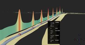
Simian SDA. Images from Intecsea. |
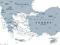
West Delta Deep Marine (WDDM– BG Group 50 %, Petronas 50%) is off the north Egyptian coast, abutting the Rosetta block, approximately following the 200m seabed contour.
The development, which was the first deepwater field offshore Egypt, extends from around 300-1200m, water depth, employing diverless subsea technology within confines of the block.
The initial development commenced in 1999, and was dedicated to the domestic market in Egypt, with the core infrastructure of the main transmission pipelines from the pipeline end manifold (PLEM) to the shore reception facilities, built at Idku, near Alexandria. It was designed to allow for expansion from the initial 700 MMscf/d to 2000 MMscf/d. Subsequent phases were to be dedicated to the adjacent LNG plant and to maintain a production plateau throughout a field life of 25 years.
Intecsea has worked in partnership with the joint venture company operator Burullus (EGPC 50%, BG Group 25%, Petronas 25%) and undertaken the conceptual design, front-end engineering design and the technical assurance for all phases of WDDM development to date and is currently supplying a technical assurance support team to Burullus on the latest Phase IXa development.
Fit for purpose from day one
To provide a sound and structured development, the emphasis was on using proven, qualified technology, simple fit-for-purpose designs, with no single point failure causing a complete shutdown of the subsea system.
The gas produced from the WDDM reservoirs is sweet, but pressures and temperatures are such that there is a continual risk of hydrates from the produced water. Continuous mono-ethylene glycol (MEG) injection, complete with corrosion inhibitor, is provided via dedicated pipelines routed to each field area. In addition to the produced water, the Sapphire field also produces a significant amount of condensate that is required to be extracted prior to the gas entering the domestic market or the adjacent LNG plant.
Pipelines on WDDM are carbon steel ranging from 10in for well flowlines, to 20in and 26in-diameter for infield pipelines.
These infield flowlines eventually terminate at the PLEM, where 24in and 36in-diameter pipelines provide the export capacity to the onshore plant.
With fishing activity possible, the larger pipelines are designed for fishing gear pullover loads and the smaller 4in lines and umbilicals are trenched. Subsea structures in the shallower waters are designed to be overtrawlable, while in deeper waters, the structures are upright. Initially considered for up to 200m water depth, this has been increased to 400m for phase IX.
Subsea equipment includes horizontal trees, with the flowloop connector hub mounted directly on the tree body, and remotely installed tie-in jumper spools connecting the trees and manifolds to the infield flow lines.
 |
|
Scarab Saffron phase UV SDA. |
The first fields
The Scarab/Saffron fields were the first to be developed, using eight wells connected to two production manifolds with an Aker Solutions (formally Kvaerner) electro hydraulic multiplexed control system expandable by two wells and one manifold. These are controlled directly from the shore terminal, 90km away, with a distribution unit and “repeater module” at the manifold center 80km from shore. Twin 20in main export pipelines commence at a water depth of 415m and run for 30km to the PLEM at a depth of 95m, where 24in and 36in export lines convey the product to the shore terminal. A 4in pipeline conveys MEG from shore to the field for hydrate inhibition by direct injection at the trees. The Scarab/Saffron fields started producing in 2003 at about 700 MMscf/d.
 |
|
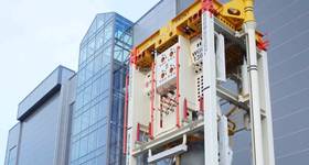
Simian platform. |
The Simian/Sienna (Phase II) and Sapphire (Phase III) fields were the first planned expansions to provide gas to the new LNG plant, with six wells at Simian, two at Sienna, and eight at Sapphire. Each field area had two manifolds. Designed expansion for each field was again four wells and one manifold. The flows from these fields are brought together at the PLEM where gas from all the fields is commingled into the export pipelines to shore.
For the phase II and III developments the contracting strategy was from an offshore management contractor, phase I, to a total turnkey offshore EPIC, resulting in a change of umbilical and control systems supplier.
The subsea wells are controlled via a GE (formally ABB Vetco Gray) electro hydraulic multiplexed system, with controls, hydraulic power and methanol injection equipment mounted on a controls platform, strategically positioned in shallower water close to the PLEM.
Phases II and III added a further production capacity of 1400 MMscf/d, allowing overall WDDM production to exceed 2 billion scf/d, the nominal plant capacity.
Phase IV: outgrowing the infrastructure
Phase IV was the first expansion of an existing field area and added seven wells and two manifolds to the Scarab/Saffron production hub, which exceeded the initial control system design.
The expansion was complicated by the requirement to incorporate west gas flowmeters (WGFM) and operator adjusted glycol control units (GCU), previously ROV adjusted, following their introduction on phases II and III. In addition, the original subsea electronics module was now obsolete and the replacement required a revised “repeater module” to accommodate the communications differences.
The incorporation of a new design of communications repeater module was relatively straight forward; a structured qualification program being implemented to prove the design prior to installation.
The other issue was providing sufficient power, although with the existing dual power supplies the system was still functional. However, single channel operation, with the system as configured, was not possible; effectively removing the system redundancy. Typically all sensors within the subsea control module (SCM) were powered up on the application of system power, allowing data to be displayed as soon as communication is established. In the case of the WGFM, which had significant inrush and steady state current, data is only required once the well is producing. Although it is not the control system vendor’s normal process, modifying the software to have the WGFM “OFF” on power-up reduced the system loading to an acceptable level for single channel operation.
Process expansion to allow the two additional manifolds to be located adjacent to the existing structure was straight forward and achieved using tie-in spool bases, which provided the necessary separation.
Phase V added onshore “boost” compression and had no impact on the offshore development where the next expansion, WDDM phase VI, was for the addition of the Sequoia field. Although comprising of six wells, only three, Sequoia North, were associated with WDDM, being connected into the Sapphire, phase III, hub, both from a process and controls aspect.
Within the original WDDM architecture, the phase III, Sapphire hub, umbilical was configured with separate power and communications cables to support future developments in the Sequoia and Saurus reservoir areas. Unfortunately during the early operation of the Sapphire field, one of the umbilical power cables failed, and in order to restore the dual supplies, one of the future cables was utilized. However, the three-well, one manifold North Sequoia expansion was within the original Sapphire control system expansion capacity and was thus easily incorporated into the existing Sapphire network. The process connection was into the Sapphire M2 manifold utilizing an existing expansion connector on the main header.
 |
Phase VIII: Enter HIPPS
Phase VII added onshore “main” compression and an additional 36in. export line connected by hot-tap to the 26in. Sapphire export pipe line and had no impact on the subsea control system.
The phase VIII expansion of the WDDM field was carried out in two campaigns; VIIIa added nine wells and three manifolds to the Sapphire and Scarab / Saffron areas and VIIIb added a further eight wells, two with high integrity pressure protection systems (HIPPS), and one manifold to the Simian area. This spread the wells, across both control system vendors, and in theory exceeded the original design capacity. Field expansion has brought in new, higher pressure, reservoirs requiring HIPPS to protect the existing pipe line infrastructure.
Where possible, the system has used common designs throughout the development of the field. And in the case of the Sapphire area, which is 24km from the platform, has the same power supplies as installed for Simian, 52km from the platform. This commonality would allow the control system for the Sapphire field to be expanded to power, and control, the additional wells and manifold that would be associated with the Scarab area, 46km from the platform via this route.
Analysis indicated that changing the topside, platform location, power transformers, using actual data, managing sensors and revising the subsea distribution would provide an acceptable level of system availability.
Process expansion was conventional in that each area remained separate, resulting in the Scarab field being controlled through two different control systems interfacing to the plant integrated control and safety system, requiring various process and field area shutdowns to be included in both subsea systems.
Phase VIII would also be the first expansion for the Simian area, meaning that original design expansion would still be available. Although expansion of the process was conventional with regards to architecture, the new wells brought in new, higher pressure, reservoirs which necessitated the addition of the HIPPS.
Process network expansion
Although phase VIII had maximized the system from the control systems aspect, there was still a need to expand the process network, with phase IXa requiring the incorporation of a further 16 wells, nine requiring HIPPS, and the associated infrastructure to maintain the production plateau.
Expansion of the process network has been straight forward with only one additional manifold being required. However, the expansion of the control system required significant upgrade.
Conceptual studies indicated that the most cost effective option was to utilize the unused Saurus equipment on the platform and install a new umbilical to the field at the Scarab area and to reconfigure the subsea distribution to balance out both power and communications distribution.
Future developments
Studies are in place for a tie in of the BP West Nile Delta Libra-Taurus fields; demonstrating that Burullus, and its operator, continue to support the development of new supplies of energy for the Egyptian domestic market.

David Smith joined the subsea controls industry in 1991, following 15 years in the defense sector. He was involved with the development of control systems for several Norwegian and UK companies and in 2001 joined INTEC to work on the conceptual subsea controls and umbilical design for the next phase of a major gas development offshore Egypt in the Eastern Mediterranean, and he has been there since working as Group Leader, Control Systems, though from the conceptual phase to commissioning the plant on site in Egypt.
 Subscribe