2H Offshore’s Mike Campbell and John Gaver discuss design challenges of riserless well intervention systems and best practices.
 |
 |
|
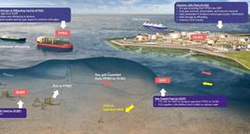
Figure 1 – Traditional vs riserless intervention systems. Images from 2H Offshore. |
Riserless coiled tubing well intervention is growing in popularity within the industry. These systems have the benefit of being significantly less expensive when compared to traditional well intervention systems. While labeled “riserless,” they are in essence riser systems and should be treated accordingly. However, they have additional unique design challenges. Due to high plastic strains in the reeled coiled tubing and dynamic loading at the hangoff location, fatigue failure is a sizeable risk.
Traditional invention risers are typically comprised of a top tensioned 5-7in diameter pipe. Coiled tubing is generally deployed inside the intervention riser. In riserless systems, the outer pipe is removed, leaving just the coiled tubing. A traditional intervention riser stack-up (left side) is compared to a riserless intervention system (right side) in the Figure 1.
The reeled coiled tubing is deployed over a sheave through the vessel’s moonpool or over the vessel’s side. The fluid conduit extends from the vessel to an elevation of approximately 50-75ft above the mud line. A clump weight is attached to the bottom of the coiled tubing to limit the system’s dynamic response during installation and straighten the coiled tubing as it passes over the sheave. The bottom of the coiled tubing is connected to a subsea assembly on top of the tree via a slack flying lead.
The primary area of concern in these systems is the region of coiled tubing in contact with the turn-down sheave. A typical subsea pumping operation requires the coiled tubing to undergo multiple plastic strain cycles as it is deployed and retrieved. Additionally, the coiled tubing will undergo dynamic fatigue loading during operation from the vessel motions and interaction with the sheave. The geometry of the sheave will dictate both the strength and fatigue response of the system. A smaller sheave radius will induce the following:
As a recommendation, the minimum sheave diameter should be 48 times greater than the outer diameter of the coiled tubing, as per NORSOK D-002 Section 7.5. This sizing ratio provides a good balance between the system footprint and coiled tubing structural performance.
The critical sheave locations (A, B, and the fatigue hotspot) are shown in Figure 2. When calculating the fatigue response at each location, the peel-off effect must be correctly modeled. If it is assumed that the coiled tubing is tangent to the top and side of the sheave at Point A and Point B, the fatigue hotspot would, in theory, instantly transition from having a finite curvature to having infinite curvature. This would result in a fatigue life measured in minutes rather than weeks at Point B. In actuality, the stiffness of the coiled tubing causes a much more gradual “peel off” region. The points of peel off initiation are identified with green arrows in Figure 2.
 |
|
Figure 2 – Critical pipe locations on the sheave. |
A fatigue hotspot, existing just below Point B, is the location where failure is most likely to occur. Detailed analysis of the fatigue hotspot is suggested before operations commence.
As discussed above, the fatigue hotspot will experience low cycle fatigue (defined as <1000 cycles to failure) during installation/retrieval and high cycle fatigue (defined as >1000 cycles to failure) during its service life. Calculating high and low cycle fatigue independently from each other is routinely performed. However, this approach can underestimate the fatigue capacity of the system, and correctly accounting for combined high and low cycle fatigue is critical in this application.
Miner’s Linear Damage Rule is a linear method of combining fatigue damage, which is useful if the damage is in the same fatigue domain (high or low cycle).
However, Miner’s rule becomes inaccurate when combining low and high cycle fatigue. Therefore, its sole use is not appropriate when analyzing riserless subsea pumping systems. Two fatigue damage summation rules which are useful for combining high and low cycle fatigue are discussed below.
 |
|
Figure 3 – Periodic overload strain-life curve. |
Non-linear fatigue combination methods
The power rule and other non-linear damage summation laws can be used to convert the low cycle reeling fatigue into an equivalent high cycle fatigue damage rate. This equivalent high cycle fatigue damage can be summed using Miner’s rule with the high cycle operational fatigue damage to provide an overall fatigue damage. High cycle and low cycle fatigue must be calculated independently for these damage summation rules to be applicable. The power rule and other non-linear damage summation laws are experimentally fit curves and require some material testing. The power rule is fit to the material type and geometry through the use of an exponent, p. When no experimental data is available, the power law can still be used by assuming a conservative p-value.
 |
 |
|
Figure 4: Case study – Fatigue life Sheave deployed subsea pumping system |
Additionally, the power rule requires knowledge of the loading sequence to be used. This is suitable for riserless well intervention, however, because the load sequence is predictable. Assuming all low cycle fatigue damage occurs prior to any high cycle fatigue damage will result in a conservative fatigue damage accumulation value.
Periodic overload curve
While the power rule and other non-linear fatigue damage accumulation laws only serve to combine high and low cycle fatigue, the periodic overload approach takes into account the effect of the overload cycles (reeling cycles) on the operational cycles. The periodic overload strain-life curve is developed using tests that apply periodic overloads at regular intervals so that all the applied small cycle stress/strain ranges are fully effective. When the specimen fails, an equivalent fatigue life for the small cycles can then be obtained using a derivative of Miner’s rule.
An effective strain-life curve accounting for periodic overloading is thus generated. This curve is represented by the red curve below the blue constant amplitude strain-life curve in Figure 3. The constant amplitude and periodic overload curves are the same when their strain amplitudes result in low cycle fatigue. However, the curves diverge as the overload cycles become significantly more damaging than the operational cycles. This effectively de-rates the fatigue life.
The fatigue response of an example case study from a Gulf of Mexico riserless intervention system is shown in Figure 4. The plot on the left shows the full length of the tubing, while the plot on the right shows a zoomed in view of the hangoff region. The dotted blue line represents the water line, and the dotted orange line represents the fatigue hotspot on the sheave.
The average fatigue life along the entire length of the coiled tubing is approximately 1000 years, but the fatigue life drops to approximately three weeks at the hotspot location. However, this fatigue damage is extremely localized and can be managed. To mitigate risk of fatigue failure, implementation of over-reeling is recommended, where the coiled tubing is incrementally reeled in at predefined intervals.
In conclusion, the reduced cost of riserless well intervention is becoming more attractive to oil field operators in the current oil market. However, there are challenges that must be addressed. In addition to complying with existing riser standards, there are uncertainties surrounding the strength and fatigue response at the sheave hangoff location. This article has proposed some methods of more accurately assessing the relationship between high and low cycle fatigue in the coiled tubing and operational strategies for mitigating the risk of fatigue failure.

Mike Campbell is a vice president at 2H Offshore and has focused his career on riser and conductor systems for close to 20 years. He has extensive experience in the specification, design, riser monitoring and integrity management of a variety of riser and subsea systems. Campbell is also a director of Clarus Subsea Integrity Inc. He is a graduate from the University of Sheffield and is based out of Houston.

John Gaver has worked as an engineer at 2H Offshore for 2.5 years. He has participated in multiple coiled tubing and riserless well intervention workshops. He is an active member of the API 17G2 – Riserless Well Intervention Committee and presented on riserless well intervention at the Offshore Well Intervention Conference held in Houston this fall. He is a graduate from Georgia Tech and is based out of Houston.
 Subscribe