Denise Smiles, of Optical Metrology Services Ltd (OMS), discusses how to correct internal HiLo misalignment between butted pipes.
 |
|
OMS’ automatic pipe end dimensioning tool. Images from OMS. |
Deepwater oil and gas pipeline projects present many challenges. As deepwater oil field developments increase around the world, fixed facilities are not always a viable option. Floating production systems are therefore increasing in number, which require unsupported riser designs.
However, these unsupported risers are subject to significant loads from ocean tides, storms, currents and swells, creating a highly dynamic environment for the steel catenary riser (SCR). This, in turn, necessitates design and fabrication processes that mitigate stress and fatigue factors. Ensuring the integrity of fatigue-sensitive SCRs is therefore one of the most challenging aspects of deepwater development.
A number of highly critical aspects of the pipe fabrication process must be guaranteed to be correct. One of these is the internal HiLo misalignment between butted pipes.
Minimization of HiLo contributes to a good weld and decreases stress at the weld joint. Typically the HiLo is required to be less than 0.5mm in fatigue-sensitive pipeline sections. In engineering terms, this is a considerable challenge, particularly given that the pipe used in these applications is often seamless, which means it inherently has wall shape and thickness deviations.
 |
|
Internal HiLo misalignment between butted pipes. |
One method of dealing with HiLo misalignment is to counterbore the pipes, but this might not be a viable method of controlling pipe geometry due to cost considerations or to limitations on pipe wall thickness. If counterboring is not viable, how can a pipeline contractor ensure that the pipe fit-up, welding and pipelaying processes run smoothly with minimal interruption?
To help prevent these kinds of bottlenecks, save costly delays and to minimize project risk, pipe end geometry can be captured, recorded and analyzed. Automatic, laser-based measurement tools can be used to measure geometrical features of pipe ends, normally performed onshore, although this process sometimes has to take place on a cargo barge. This measurement data, if used correctly, can then help to ensure that pipes delivered into the bead stall will fit together easily and within the welding specification requirements. Better weld quality will lead to fewer cut outs and repairs, reducing costs for the pipeline contractor.
 |
|
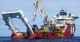
Pipes being unloaded from a supply barge to the pipelaying vessel. |
The measurement tools can be used to measure the inner diameter (ID), outer diameter (OD) and wall thickness (WT) of pipe ends in rapid time. Typically, several thousand ID and OD measurements of a pipe end can be measured simultaneously in less than 10 seconds, enabling hundreds of pipe ends to be measured in one shift. In some circumstances, pipe ends can be measured in stacks. This means less time on site and less pipe handling (reducing costs), thus minimizing delays and costs for the pipelay contractor. Laser measurement tools are also very accurate (typically to 0.05mm).
Data from laser measurement tools can be made available to pipe optimization software, which will include some sort of simulation or sequencing software. SmartFit, the winner of a Queens Award for Innovation in 2014, is a system developed by OMS for managing pipe preparation and fit-up in readiness for welding prior to pipelaying. Used predominantly in the oil and gas industry, this system ensures accurate fit-up of pipes prior to welding and laying in trenches, thus preventing environmentally damaging leaks. In parallel, OMS has developed bespoke laser measuring equipment and methodologies with supporting software, for optimizing pipe fit-up. The service reduces costs for customers through faster pipelaying and improves quality by eliminating misaligned pipe ends.
Each pipe end is measured, identified and entered into the pipe optimization software, which analyses the fit-up of pipes and allows the operator to mark the best rotational position on each pipe end. In the bead stall, these marks are aligned to immediately achieve the best rotational position so that misalignment is minimized and the project HiLo is easily achieved.
 |
|
The SmartFit software has the ability to sequence single and multiple pipe ends (i.e. doubles, triples and quads). |
Any problem pipes that won’t fit at a specified HiLo are also indicated and can be re-sequenced or removed completely so that fit-up problems do not occur in the bead stall. Production delays due to misaligned pipes are avoided.
Experience shows that with typical flowline HiLo limits — and using typical seamless line pipe that has not been counter-bored — fit-up issues can occur regularly. For a HiLo of around 1.0mm to 1.2mm, problems are likely to occur every 10 to 20 pipes (this varies according to the exact type of pipe). Using pipe optimization software enables the required HiLo’s to be achieved in the bead stall without trial and error. It also identifies problem pipes in advance, so that this can be removed from the pipe welding sequence, therefore avoiding any problems in the bead stall.
Elements of pipe optimization can be deployed in various ways to suit the practicalities of different production processes, both onshore and offshore. OMS has applied the system aboard a wide variety of pipelaying vessels and spool bases around the world.
 |
|
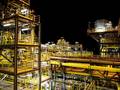
End dimensioning of pipe ends at an onshore pipe coating yard. |
Case Study: Offshore pipe fit-up
In 2014, OMS was asked by a pipeline contractor to provide pipe fit-up services for a deepwater pipelaying project off the coast of Australia.
Project details
The customer had already carried out end dimensioning of the pipes prior to OMS’ involvement. After measurements were taken, the customer deemed the pipes to be satisfactory and within the manufacturing specification. Welding of the pipes began offshore on the pipelaying vessel, with a target of 40 welds per day. Unfortunately, this target was not achieved due to poor pipe fit-up leading to excess HiLo. The peak weld rate at that time was approximately 15 welds per day.
OMS deployed a team of three operators direct to the pipelaying vessel. This meant that there was no opportunity for upfront analysis of pipe measurement data or reporting. Pipes were measured onboard the pipelaying vessel and support barges. One OMS software operator was required per shift to manage pipes into the bead stall. Two OMS measurement operators were required per shift until all the pipe profile measurement data had been collected (after which they were demobilized).
OMS numbered the pipes in the pipe stack (prior to beveling) to sequence the pipes ready for the riggers to collect. No extra pipe handling was required here, as only planned pipes were moved. Rotation marks were then applied to the pipes once they were placed on the ready rack.
Using pipe optimization software, it was found that most of the pipe joints would fail the acceptable HiLo criteria in multiple positions. However, the project HiLo could be achieved at certain positions when the pipes were rotated. In the following example, possible misalignment was 0.4mm at best rotation, but up to 1.3mm at worst. Result: 300% increase in weld rate.
All pipe joints sent through to the bead stall were within the client requirement of 1mm HiLo. The weld rate was increased to an average of 40-45 welds per day — an increase from the initial rate (i.e. 15 welds per day) of 300%.
In addition, OMS was able to assist with traceability issues, including identifying any pipe numbering duplicates or errors. OMS not only helped speed up the welding process through the time saved in lining up the pipes, but also helped to reduce the number of weld repairs and cut-outs.

Since joining OMS in 2006, Denise Smiles has been actively involved in the execution of many deepwater oil and gas projects that required improvement of dimensional tolerances, fit-up solutions in the firing line and delivery of specific pipeline architectures to ensure best fit-up with difficult pipes, including Gorgon (Chevron), Quad 204 (BP), Wheatstone (Chevron), Ichthys (Inpex), Jack & St Malo (Chevron), Julimar (Apache) and Laggan-Tormore (Total). Smiles was appointed CEO of OMS in 2014. She holds an MA in business administration and management.
 Subscribe