As gas wells mature and the produced gas becomes less able to carry water from the well, a decline in flow rate and production to rates below the anticipated decline curve often results. Bert Lugtmeier and Kees Veeken from Dutch operator NAM along with Weatherford’s Rodger Lacy describe how a newly devised system makes it possible to continuously inject production-enhancing chemicals into the well through the safety valve while maintaining full control of the surface and subsurface safety equipment.
Typically, production-enhancing chemicals can be injected into a well to restore production. However, when a surface-controlled subsurface safety valve (SCSSV) is in the well, as is the case in most offshore wells, there is no way to get the chemicals into the well below the SCSSV at the perforations.
Working closely with Nederlandse Aardolie Maatschappij (NAM), Weatherford International has developed the Renaissance Weatherford Capillary System (WCS) Opti-Chem safety system, which makes it possible to continuously inject production-enhancing chemicals into a well through the safety valve while maintaining full control of the surface and subsurface safety equipment. The new system incorporates a capillary string inside the tubing and uses the company’s RENGATE wellhead penetration, which creates a continuous injection conduit from the surface to the production bore of the well.
NAM recently used the system in one of its North Sea wells to restore production of nearly 3.18mmcf/d without an expensive workover.

Addressing liquid loading
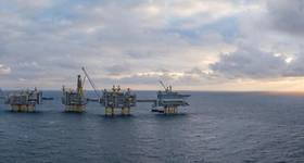
The well, located in the Dutch sector of the North Sea, was originally completed in 1976 and side-tracked in 1996 and completed with a 5in production string with a 3.81in safety valve landing nipple installed in the tubing string at 541ft depth. The christmas tree is a solid block 71/16in x 41/8in, 5000psi, installed with a 4in backpressure valve profile in the tubing hanger. The total depth of the well is 11,000ft.
The well was completed as a high-rate gas producer, but by 2008, it was producing intermittently because of liquid loading.
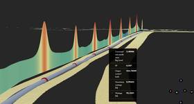
Liquid loading occurs when the inability of the produced gas in a well to remove produced liquids from the wellbore causes the liquid to accumulate in the well, leading to an eventual reduction in production. The phenomenon can occur very suddenly, sometimes causing production to drop to zero in less than 24 hours.
Liquid loading is typically alleviated through deliquification applications, in which a foamer or surfactant is added to the produced fluid to reduce its density and surface tension. The surfactant can be delivered by soap sticks, batch treatments or continuous injection. In wells with packers, continuous injection takes place through a capillary string, which is usually made up of a chemical injection valve, a capillary string (usually 1/4in or 3/8inOD) and a capillary hanger at surface. The capillary line is snubbed into the well similarly to a coiled-tubing snubbing job. This method has not been applicable in wells with functioning SCSSVs because the capillary string could not be run through the safety valve.
In 2008, NAM launched a project to appraise several deliquification techniques and select the most effective one for eventual use offshore. The techniques included automated intermittent production, velocity string production, and continuous foam injection.
Continuous foam injection was subsequently validated in onshore operations, and a pilot offshore installation was designed.
To address North Sea regulations that mandate use of a full safety system, including both surface and subsurface equipment, the design team researched systems that would allow continuous foam injection to the perforations without compromising the integrity of the safety valves.
The first system installed offshore was designed to have foam injected via the safety valve control line using a backpressure valve to maintain injection pressure at the SCSSV operating pressure.
Two different approaches were tried. The first method used a foam insert sleeve incorporating a bypass to the capillary line below and a safety valve landing nipple into which a smaller size standard safety valve could be landed. The second approach used a safety valve with a built-in bypass to the capillary line below, which involved modifying the existing safety valve.
Although both systems worked, restrictions on foamer choice and system reliability and repair frequency led NAM to decide that future installations should be based on a through-tubing foam injection system that would provide a corrosion-resistant route to the top of the perforations, completely separated from the safety valve system. This approach would allow for a wider choice of foamers, improve system reliability, and significantly reduce required foam injection pressure since it would not have to operate at SCSSV hold-open pressure.
Anatomy of a solution
Working closely with NAM, Weatherford designed the WCS safety system to meet all stated requirements. The system, to be conveyed on conventional slickline, would be installed in the existing safety valve landing nipple and be operated using the in situ control line. It would provide a flow path for chemicals through the safety valve, totally independent of the safety valve control system. It would permit the upper section of the capillary string above the SCSSV to be connected and disconnected repeatedly.

Meeting the design criteria meant using two separate control/capillary lines. Dual lines would help avoid potential contamination and corrosion damage to the safety valve system. They would also help maximize safety and control installation costs by allowing the existing emergency shut-down system at surface and at the wellhead to remain undisturbed.
The design of the new system was based on the field-proven, retrofit Renaissance Weatherford Damaged Control Line (WDCL) damaged-control-line safety valve, which incorporates a control line inside the tubing string. A WDCL system installed in a NAM offshore well in 2009 continues to function satisfactorily, and the system has also been run for an affiliate company in the UK North Sea.
The WCS system incorporates a 1/4in or 3/8in capillary line that runs down the center of the tubing to a pod in the wireline retrievable safety valve that directs the flow of chemicals through the valve to the injection line below. At the end of the capillary line is a centralized stinger with a hydraulic wet-connect that joins the capillary to the mating connection in the pod. A bi-directional barrier incorporated into the wet-connect can be opened only when the male and female components are mated, which allows the capillary line to be snubbed into a live well as in a coiled-tubing snubbing job.
A hazard and operability (HAZOP) study conducted by NAM confirmed the suitability of the wet-connect as a barrier device under all possible well and operating conditions.
The wet-connect can be both mated and unmated, enabling the capillary to be removed if necessary. It is locked in place when pressure is applied to the capillary string. The wet-connect design eliminates complications and additional leak paths that a hydraulically operated latch would create. A unique capillary hanger is used to hang the capillary line from the modified wellhead and the safety valve. The control-line hanger lands in the tubing hanger backpressure valve profile and seals in the modified lower master valve. Its bypass area is similar to that of the safety valve.
Surface access to the capillary line is provided by modifying the wellhead in a way that also provides the correct profile for the capillary hanger. The company developed a new wellhead penetration, the system that is installed in situ without changing the original wellhead geometry. The design allows a penetration to be made through the lower master valve (LMV) bonnet and lower seat, which does not affect either the functionality or pressure rating of the LMV. There is no need to lift the wellhead or insert spool pieces, or otherwise modify the surface installation, which results in a quick, cost-effective procedure.
The valve rebuild can be installed by a qualified service technician.
Once the control-line hanger has been landed in the tubing hanger profile and sealed in the modified wellhead, a conduit for continuous chemical injection exists from the surface to the chemical injection valve on the bottom of the capillary string at the perforations.
In addition to facilitating installation of a capillary line for continuous chemical injection, the modified wellhead concept is applicable to existing wells that have a damaged or blocked control line. The entire system can be removed after the well has been depleted.
First offshore installation
The first offshore installation of the WCS system took place in November 2010. The wellhead modification was the first operation of the installation sequence. The well was secured with multiple barriers in accordance with NAM and North Sea policy. The LMV was disassembled and the modified pairs installed. The LMV was then reassembled and tested.
Next the capillary tubing was run to the calculated depth to place the injection point at the desired depth in the well. The capillary tubing was cut and the safety valve was connected to the capillary string. The final run to the safety valve landing nipple was performed on slickline.
The control line stinger that connects the capillary tubing to the safety valve was picked up and run in the hole with the capillary string. The safety valve was tagged and space out was calculated. The capillary tubing was then cut and the control line hanger connected to the capillary tubing.
The final run to land the control line hanger in the modified wellhead was carried out on slickline, and the safety valve was function tested.
After installation, the well was suspended until the surface chemical injection system could be installed on the platform. Surface equipment installation was completed in March 2011, and NAM then began pumping the surfactant. The well responded very favorably and has been on line, producing at nearly 3.18mmcf/d since the startup of continuous chemical injection.
The reliability of the third party chemical injection valve is critical to the success of the system, and after months of successful production, the pressure to inject the chemical started to increase. This indicates a possible plugging of the chemical injection valve at the bottom of the capillary injection string.
Weatherford and NAM are working closely to develop a more robust chemical injection valve to solve this issue.
Because of the initial success, the companies have continued their close working relationship.
Major milestone
NAM has ordered more of these chemical injection systems as part of an on-going campaign to increase gas production by dewatering older gas wells, and Weatherford has begun the installation of a five well campaign on the Vulcan platform in the UK sector of the North Sea. The entire installation process represents a major milestone in moving continuous chemical injection offshore in Europe. OE

Once the control-line hanger has been landed in the tubing hanger profile and sealed in the modified wellhead, a conduit for continuous chemical injection exists from the surface to the chemical injection valve on the bottom of the capillary string at the perforations.

Bert Lugtmeier is a senior production technologist with NAM. His current technical interest is gas well deliquification and well completion innovation in general. He has a BSc in mechanical engineering and worked for Shell both in the Netherlands and the UK for 30 years, focusing on reservoir engineering IT, drilling and production equipment engineering, well services, production programming and production technology.

Kees Veeken is a principal production technologist for offshore gas wells with NAM. His current technical interests include gas well deliquification and tight gas development. He has worked for Shell as a production technologist for 25 years both in R&D in the Netherlands and the US and in operations in Oman, Malaysia and the Netherlands. He earned a PhD in molecular physics at the Radboud University, Nijmegen.

Rodger Lacy is the global product line manager for the Weatherford Renaissance Safety Valve, having been involved with the development of this new tool system since it NAM first suggested it. He has 35 years’ industry experience under his belt, all of it in completions, and served as Weatherford International’s country manager in Nigeria prior to being stationed in the Netherlands in 2006.
 Subscribe