When people think about X-rays, they most likely think about hospitals or maybe even pipeline inspection. Elaine Maslin examines how X-rays could be deployed in a wellbore near you.
 |
|
Test images. Images from Visuray. |
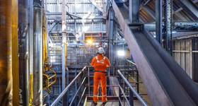
X-ray technology is being taken downhole to help visualize what is happening in the well, such as stuck or faulty downhole equipment or damaged casing and maybe even formation evaluation.
Existing techniques for seeing what’s happening downhole include dropping lead to create an impression of equipment in the hole, ultrasonic imaging, which relies on knowing the specifications of the well fluid at the investigation depth, and using cameras in transparent well fluid or gas filled wells, which can mean spending time cleaning and preparing the well.
Malta, Stavanger and Houston-based Visuray hopes its VR90 tool, incorporating a thermionic X-ray tube, will supersede those methods by providing 2D and 3D images from inside the well, without the need to condition well fluids or to have detailed knowledge of the inside geometry and physical properties of the materials inside the well.
But, because X-ray imaging traditionally involves access to both sides of the object being X-rayed, Visuray has had to develop a new technique – fluid-based surface imaging. It has the X-ray source and detector positioned on the same side of the object. But, because steel or metal objects absorb the photons emitted, it is mostly radiation reflected by the fluid that will be picked up by the detector.
To deal with this, Visuray’s fluid-based surface imaging converts the “noise” created by the fluid backscatter into a reconstruction of the surface of the object in it, based on the amount of scattering arising from the fluid between the source/detector and the object.
The firm’s tool stems from work by Phil Teague, a graduate in Physics and Astrophysics from the University of York, England, who started the company in 2004.
“The physics are quite novel,” says Jack Johns, field test coordinator at Visuray, told last year’s Production Optimisation conference in Aberdeen. “Normally you transmit X-rays from the source to detector [passing through the target]. As we’re in a well, you can’t get the detector behind the source, so need to use the backscatter [off the target].
“We illuminate the area in front of the tool in the well. Backscatter goes through pin holes in front of the detector and projects an image on to detector,” he continues. “In essence, you create a 3D representation of the fluid in front of tool or well architecture. So you know what is there – it could be a safety valve, collapsed casing – by reconstructing and inverting the image.”
To produce X-rays, the tool has been developed to produce whatever high-voltage power is required, from power passed downhole through the wireline. This also meant an active downhole cooling system had to be developed. The company is keeping a tight lip about both technologies. “As far we know it is the first down hole actively cooled tool,” Johns says.
Visuray says that there’s no residual radiation to humans, because the tool is always switched off near or at the surface.
The firm initially worked with support from Statoil, BP and Shell, proving the technology. In 2005, the first successful laboratory image was taken through mud. In 2007, a 4m-long, 9in-diameter prototype was built and run downhole at the Ullrigg test well just outside Stavanger.
In 2014, the first working, field operating tool was created and in early 2015, after seven years and about US$90 million investment, a 3 5/8in commercial version of the same tool –the VR90 – was successfully tested in a well in Germany.
The tool measures 8.38m-long, with three sections (telemetry, cooling and high voltage section) and 9.2cm-diameter and is compatible with tractors, strokers and coiled tubing, capped at the end by a 2cm-thick Beryllium window (Beryllium has high transparency). It operates at ambient temperatures up to 150°C or 300°F and pressures up to 20,000 psi.
It includes a custom-built, shielded thermionic X-ray tube, operating at 180 kV and an electron beam current of 1 mA. The electronic detector has six individual detector tiles, each divided into 128x128 pixels, with pixel size at 100 µm by 100 µm. Each detector tile has its own 350-µm diameter pinhole to direct backscattered X-rays onto the tile.
Data from all six tiles are combined to create a single composite image spanning the entire field of view. The composite image may be displayed as a 2D depth map image or rendered as a 3D surface reconstruction.
During the tests in Germany, 11 separate runs were made to conduct tests and create images at depths of up to 2100m (6890 ft) and temperatures of up to 100°C (212°F).
The first commercial operation was run late 2015 for TAQA in an onshore gas storage well. Two complete tool strings sent to the wellsite have performed a total of 13 runs with a maximum temperature of 85°C up to a depth of 2100m. The tool successfully imaged the top of a coiled tubing disconnect with millimeter accuracy and helped TAQA to plan fishing operations in the well. With the 3D images created, firms could then design a fishing tool.
During lab testing in different fluids, from water to brine and then oil, showed that similar images could be produced of the object, at up to 10cm in a variety of stand well fluids, with 1mm resolution. How the tool performed at different distances from the object has also been tested, including sand, which still worked at up to 5cm.
Visuray is also working on other projects using its X-ray technology, including cement evaluation (VR360) and formation evaluation.
 Subscribe