Dr Premkumar Thodi, Mike Paulin, Duane DeGeer, and Glenn Lanan, INTECSEA Canada, examine examine the potential of external distributed sensors using fiber-optic cable systems.
 Multiple offshore Arctic fields have been developed over the past three decades, and the world demand for oil and gas will continue to drive development. The implementation of reliable Arctic operational strategies will allow additional offshore prospects to be developed.
Offshore pipeline technology is being advanced to accommodate Arctic challenges. Although arctic pipelines are designed not to leak, high-bending strains due to ground movements could result in leaks. Large leaks can easily be detected using computational pipeline monitoring (CPM) systems, but small leaks may go undetected, especially when the pipelines are located in remote environments or under seasonal ice cover. In these cases, external leak detection systems (LDS) can augment CPM for increased, overall leak detection reliability. However, there is limited documentation of successful external LDS performance offshore.
Leak detection challenges
Arctic offshore pipelines are subjected to many environmental loading conditions: ice gouging,strudel scour, frost heave, permafrost-thaw settlement, and wave/current loading if the pipelines are unburied. Potential failure mechanisms include fracture, burst, buckling, and fatigue. Trenching and burial are the principal design methods for protecting Arctic pipelines from environmental loading.
Arctic pipelines may be in remote locations and/or under seasonal ice cover. Thus, leaks must be minimized. An effective external LDS can mitigate leak-risk to human life, the environment, reputation, and financials.
Arctic pipeline leak detection challenges include:
 Considering the Arctic’s environmental sensitivity, continuous leak monitoring may be preferred rather than periodic leak testing. Installation of continuous leak monitoring systems may help operators in permit application and regulatory review. Rapid and reliable leak detection and location identification are important aspects for safe arctic hydrocarbon development.
Existing technologies
LDS technologies can be classified into: internal or external systems (Figure 1). Internal systems use field sensor data to monitor internal pipeline parameters: pressure, temperature, viscosity, density, flow rate, contamination, sonic velocity, and product data at interface locations. Usually, these systems are installed along with the pipeline and other data acquisition systems. The data acquired are analyzed to determine flow conditions and potential loss. The systems quickly detect large leaks, but have limited ability to detect small, chronic leaks. Internal leak monitoring system methods include pressure/flow monitoring, acoustic pressure wave analysis, mass balance (MB), pressure balance (PB), statistical methods, realtime transient monitoring (RTTM), extended RTTM, bubble emission method, pressure safety low (PSL) switches, and annulus monitoring in pipe-in-pipe systems.

External systems measure physical properties around the pipelines. These include sensors for vapors, capacitance, temperaturedifferentials, biosystem, remote detection, acoustic, fluorescence, optical, and fiber-optic cables (FOC) methods. Some types are used as point sensors and others are mounted on ROVs/AUVs/towed systems to patrol for leakage. A recent development is to deploy a sensor array or continuous FOC along the pipeline length (see panel, right).
Internal LDS are well-established for detecting large leaks. However, sensitivity drops during operations that introduce pressure/flow variations (eg startup, shut-in, valve closures, transient flow, etc). These events can be misinterpreted, leading to false alarms. Such systems can be integrated into a pipeline’s SCADA to record all large leaks (typically, above 1% of nominal flow rate). Systems usually detect large leaks in 30 seconds and small leaks within 24 hours.
External LDS can quickly detect and locate small leaks below the minimum thresholds of internal LDS, and provide information for risk mitigation. Depending on the technology, some external LDSs have limitations including:
FOC sensors overcome most of these limitations by detecting and locating leaks along a continuous optical fiber. Multiple leak events can be detected and accurately located. FOC has minimal external power or communication requirements, no pressure differential requirements, and is immune to electrical interference.1 Other advantages of FOC systems include high sensitivity, accurate leak-location in all pipeline conditions, reduced false alarms, and applicability for continuous monitoring on long buried pipelines.

FOC distributed sensors
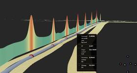
FOC distributed sensors have high potential for use in arctic pipelines. Liquid hydrocarbon leakage generates a local change in temperature that can be captured by distributed temperature sensing (DTS) systems with good spatial and temporal resolution. Similarly, the sound signature generated by leaking hydrocarbon can be measured using distributed acoustic sensing (DAS) systems. Inelastic Raman and Brillouin backscattering principles are used in DTS, whereas the Rayleigh backscattering principle is used in DAS (Figure 2).
FOC distributed sensing theory FOC installed along the pipeline can measure thermal and acoustic anomalies in real-time. This continuous placement replaces multiple sensors along the pipeline and provides backscattered signal at the source after sensing anomalies. By analyzing the backscattered signature, leak presence and location can be identified to alert the control room.
In FOC distributed sensing, the optical time-domain reflectometer (OTDR) principle finds leaks (Figure 3). An optical signal is emitted into the fiber; a sensor receives and measures the light backscattered to the source. The received signal shows an exponential decay with time from attenuation. The time interval between the emission and backscattered detection can be easily converted to distance to the leak.
Distributed temperature sensing
An oil leak produces local environmental warming, while a gas leak produces local cooling from the Joules-Thompson effect. DTS can be based on inelastic Raman or Brillouin scattering (Figure 2). In Raman systems, thermallyactivated vibrational modes result in spontaneous inelastic lightscattering, following Bose-Einstein statistics.4 The information about the leak-generated temperature at any point along the fiber can be obtained by measuring the lightsignal powers scattered at the anti-Stokes and Stokes wavelengths, and by evaluating the ratio between these two powers.
Raman-based systems require some filtering to isolate the relevant frequency components. Since the magnitude of spontaneous Raman scattered light is low, high numerical aperture multimode fibers can maximize the guided intensity of backscattered light.3 However, the high attenuation of the fibers limits the length of Raman systems of 8-10km.3,4 The FOC must be installed in an axial strain-free condition. Communications to surface can be through an existing subsea control module (SCM) incorporated into SCADA. Typical spatial resolution is of the order of one meter and temperature resolution is 0.2°C.3
Distributed acoustic sensing
DAS uses a monitoring instrument at one end of the pipeline and two or more fibers within a FOC bundle to detect leakage. The FOC acts as a distributed hydrophone system that picks up sound from leakage. When a leak’s sound signature is detected, location information is sent and an alarm is triggered. OTDR in the Rayleigh band monitors acoustic signals. The backscattered signals, measured as a time function, detect and locate leakage.
Rayleigh-based DAS systems have monitoring capabilities up to 25-50km without repeaters with a single instrument at one end of the pipeline.2 Communications to surface can go through an existing SCM or by an acoustic link in SCADA. The DAS system may have a limiting threshold because of background noise. However, DAS does not require the cable to contact leaking fluid, and thus it may be promising for Arctic pipelines. DAS sensitivity to detecting a small, chronic leak will be affected by spatial resolution, coverage length, leak size/strength, background noise, acoustic signature, soil conditions, cable positions, distance from leak, and internal vs external pressures.
Installation and maintenance
DTS and DAS have both installation and maintenance challenges. In both cases the FOC must be close to the pipeline. They are typically supplied as subsea armored cables with diameters ranging 22-35mm. The cable can be bundled with, or laid adjacent to, the pipeline.
The pipeline may shield an acoustic signal from a DAS cable on the opposite side from the leak. Therefore, more than one cable may be required for optimum DAS detection. DAS systems for monitoring buried pipelines may be affected by trench and soil conditions. While some soil may transmit sounds better, others may insulate the FOC from sound, or reflect signal back to the leak. Installation and maintenance of the repeater/instrumentation units for a trenched pipeline may need further investigation.

Oil, gas, and multiphase fluids are typically lighter than seawater, thus the optimum position for a single DTS cable will be on top of the pipeline. However, the pipeline may rotate during installation, so having more than one cable for DTS provides optimum coverage.
Pipelines with sensing cables must pass over rollers on installation vessels, subsea trenching equipment, or onshore roller equipment for on-ice installation in the Arctic. The cables must be protected from crushing or snagging on the rollers. Winter or late open-water season installation temperatures may be below the minimum-rated installation temperature for FOC (–10°C). This limit may require heating the cable during unspooling and installation.
The laybarge needs reconfiguration for simultaneous installation of cables and pipeline making modifications for equipment attachment, reels, cable handling, and cable heating. Splices and connections introduce signal losses that affect the maximum coverage length for the system. Therefore, cable connections onshore, in-water cable splices, and those at offshore facilities should be limited by maximizing the cable reel size.
Technology gaps
Key technology gaps associated with the FOC-based, Arctic, offshore pipeline, leak detection include: uncertain minimum detection thresholds, false alarm reduction, FOC on long pipelines, reliability quantification, installation, and maintenance.
Arctic pipelines are designed to safely transport hydrocarbons, but low-probability leaks pose severe environmental, safety, and economic consequences. Online leak monitoring is an important aspect of safe Arctic pipeline operation to minimize any release. Since internal LDS’s have limited capabilities to detect and locate leaks under 1% of the fluid flow, external LDS technologies may be warranted. OE
 Dr Premkumar Thodiis an engineering specialist with INTECSEA Canada. Dr Thodi gained his PhD degree at the Memorial University of Newfoundland, Canada. He has more than six years of experience in offshore pipeline engineering, pipeline leak detection, and integrity management
Buried pipelines conveying multiphase flows.
Open water and seasonal ice cover.
Installation and maintenance.
Equipment and power.
Operational management using supervisory control and data acquisition (SCADA).
Remote performance monitoring and control.
False alarms.
Uncertain minimum detection thresholds.
Background noise reduction.
Operational reliability.
Regular repair/replacement for fouling and drift.
Poor sensitive to smaller leaks.
Dependence on ocean current/ diffusion.
Difficulty in quantifying size and location of small leaks.
Requiring permanent installation.
Requiring leaking fluid-sensor contact.
Requiring differential pressures.
False alarms.
Installation and maintenance difficulties.
 Subscribe