Three Alaskan Beaufort Sea developments – BP Exploration (Alaska)'s Northstar, Pioneer Natural Resources' Oooguruk and now Eni Petroleum's Nikaitchuq – have helped establish baseline experience for future arctic frontier pipelines. As well as demonstrating technical strides, these pipelines have set industry parameters for safe, environmentally conscious offshore installation in cold-climate conditions. INTECSEA'S Glenn Lanan and Todd Cowin and Eni Petroleum's David Johnston explain how.
While development of offshore oil and gas reserves in arctic and sub-arctic regions of the world is progressing at a relatively slow pace, operational experience with the BP (Alaska)'s Northstar and Pioneer Natural Resources' Oooguruk pipelines demonstrates that offshore arctic pipelines can provide safe and reliable oil and gas transportation systems. In general, the greatest challenge for these frontier developments is their remote locations, with short duration weather windows for construction. Other impacts include unique arctic environmental load conditions and limited existing hydrocarbon export facilities. Subsea pipelines and cables are often required as part of these offshore arctic field developments for use as intrafield flowlines Or for hydrocarbon export via trunklines or tanker systems. Safe and economical design, construction and operational procedures are needed to address the unique conditions encountered for offshore arctic pipelines.
Over the last 11 years, three pipeline systems have been installed in the Beaufort Sea, offshore the North Slope of Alaska. BP's Northstar project and Pioneer's Oooguruk project have been operating for a combined total of more than 13 years. Eni's Nikaitchuq field development subsea pipeline is scheduled to start operations later this year. Each of these offshore arctic pipeline systems transports oil and gas from artificial gravel island structures to shore.
Unique offshore arctic environmental loading conditions influenced the design of each pipeline in different ways, with specific designs for pipe bundle configuration, thermal insulation and trenching requirements. Similar differences affected winter construction procedures for each project and are expected to impact future pipeline projects in deeper waters. Key operational features for each pipeline system – including routine seabed surveys, in-line inspection pigging and effective leak detection systems – also are important for continued safe operations.
These three Beaufort Sea pipeline projects provide a significant experience base for designing, installing and operating future offshore arctic pipelines. The industry can apply this experience on arctic and sub-arctic projects that have first-year sea ice, multi-year ice or potential iceberg load conditions. Well beyond the margins of the Arctic Circle or areas surrounding Antarctica, seasonal sea ice also is found at varying latitudes in both marine and inland lake locations.
Other potential applications of Beaufort Sea pipeline experience include projects that manifest complex thermal interactions with the local environment and offshore arctic projects requiring conventional marine construction procedures during the short arctic summer season.
Environmental conditions
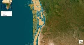
For the majority of each year, the nearshore Alaskan Beaufort Sea has landfast sea ice. The ice breaks up or melts in place starting in June; summer open-water conditions then prevail from late July through mid-October. The summer polar pack ice edge recedes to varying distances offshore based on site location, water depth and year-to-year variations or long-term climate trends.
Even during open-water season, however, ice floes are often present and their movements influenced by local winds and currents. Along much of the Alaskan North Slope coast, low barrier islands prevent multi-year polar pack ice from entering nearshore lagoon areas.
Winter freeze-up initiates in the shallow lagoon areas and forms generally smooth, stable landfast ice in sheltered areas. Ice formation then advances rapidly offshore, and this area too becomes relatively stable landfast ice with varying degrees of ridging and rubble piles by late December. The nearshore landfast ice zone can support winter ice roads and provide a work surface for pipeline construction. The durations of both the summer open-water season and winter landfast ice construction season are variable and this variability must be factored into project construction planning.
Alaskan Beaufort seabed conditions include sand, silt and clay soils, and the bathymetry gradually slopes toward the north. Irregular bathymetry is found near the barrier islands and in areas affected by seabed ice gouging: ice keel interaction with the seabed; and strudel scouring: seabed erosion caused by spring-time river waters flowing over the top of the sea ice, then draining through holes.
In water depths less than approximately 200ft, pipelines must be trenched into the seabed to avoid excessive ice loadings and to avoid more conventional sources of pipeline instability such as hydrodynamic loads, localized seabed erosion, spanning and upheaval buckling.
The Alaska North Slope shoreline is generally receding; the pipeline shore approach design, therefore, must provide adequate setback distance to accommodate this coastal erosion and to avoid potential ice override encroaching onshore facilities.
Ice-rich permafrost is found near the shoreline where the winter sea ice becomes bottom-fast out to water depths of approximately 5ft. Beyond the 5ft isobath, remnant subsea permafrost may be found at varying depths below the mudline. When subsea permafrost warms under the influence of elevated pipeline operating temperatures, the frozen water in the soil melts and the soil may consolidate and settle beneath the pipeline.
Coastal tundra, birds, fish and marine mammals in the Beaufort Sea environment also significantly influence a proposed offshore pipeline project. Sensitive arctic flora and fauna are often absent or covered with ice and snow during the winter, and where feasible, winter construction procedures can minimize environmental impacts. Winter construction methods commonly used for North Slope pipeline projects also efficiently address site-access problems common during the arctic summer for wetland and shallow-water sites.
Northstar pipelines
The BP Exploration (Alaska) Northstar offshore arctic gas pipeline began supplying fuel gas to island facilities in late 2000, and then switched to supplying natural gas for reservoir pressure maintenance purposes. Oil production flow started in October 2001.
The BP Northstar system includes a 10in diameter crude oil export pipeline and a 10in diameter pipeline supplying gas to the offshore island. The operatorinstalled the twin subsea lines as a bundle.
The offshore lines are six miles long and extend to a maximum water depth of 37ft. The lines are trenched to a minimum depth of cover, ie original undisturbed seabed to top of pipe, of 6-9ft. The trench is backfilled with local seabed soils.
Primary load conditions controlling the Northstar pipeline design and trenching requirements included seabed ice gouging for the deeper water zone outside the barrier islands and permafrost thaw subsidence for the shallow lagoon area. The project team applied limit-state design procedures for pipe bending to calculate the minimum pipeline depth of cover necessary to resist ice keel and thaw subsidence loads.
Predicted seabed soil displacements beneath the maximum ice keel gouge depth yielded a 7ft minimum depth of cover for pipe bending strains up to 1.4%. The project team calculated maximum predicted seabed permafrost thaw differential settlements of up to 2ft – at the bottom of pipe elevation – to cause pipe bending strains up to 1.1%. In both cases, conservative design analysis assumptions provided additional safety factors against pipe bending failures.
Analysis of upheaval buckling – pipe vertical instability resulting from increased operating temperatures and pressures – and strudel scour load conditions generally did not control design trench depth requirements.
The Northstar pipeline bundle design included a LEOS leak detection systemto supplement the conventional mass balance and pressure measurement leak detection systems on the oil pipeline. The LEOS system can detect very small potential leaks by sampling hydrocarbons in a semi-permeable, air-filled tube installed as part of the pipeline bundle.
The operator installed the Northstar pipelines during January through April 2000 using conventional pipelay equipment while working from artificially thickened sea ice. In water depths greater than 10ft, installation took place on floating sea ice, making control of equipment and soil loads a critical aspect of the project's success.
Trenching spoils were removed continuously and temporarily stored on bottom-fast ice. The project then reclaimed the spoils and trucked the material back to the right-of-way for refilling the trench after pipeline installation.
Oooguruk flowlines
The Pioneer Natural Resources Oooguruk flowline system started first oil production in June 2008. The subsea arctic flowline system includes a 12in by 16in diameter pipe-in-pipe multiphase production flowline; an 8in diameter insulated water injection line; a 6in diameter gas injection line; and a 2in diameter arctic heating fuel (diesel) line.
All lines were installed as a single flowline bundle. The offshore lines are 5.7 miles long and transit a maximum water depth of 7ft. The pipelines are trenched to a minimum 6ft depth of cover.
Three electrical power cables and a fiber optic communication cable are installed in a parallel trench.
Seabed ice gouging was not a controlling design factor for the Oooguruk flowline because of the project's shallow water depth and sheltered location in Harrison Bay. Instead, the flowline operating temperatures and location immediately offshore the Colville River Delta made strudel scour and upheaval buckling the controlling design criteria. The project team, therefore, focused on minimizing thermal effects on the winter sea ice and preventing upheaval buckling.
Potential flowline upheaval buckling is avoided with a minimum trench backfill thickness of 6ft of native soils placed above the pipes with a maximum design imperfection height of 1.3ft in the flowline bundle vertical profile. Greater trench bottom prop heights also were acceptable by resisting upheaval buckling through the use of real-time prop height evaluation, gravel backfill and gravel bag placement.
The project team checked allowable flowline bundle span lengths against strudel scour depressions that potentially could form above the route. While the 6ft minimum depth of cover is adequate to avoid overstressing the lines resulting from potential strudel scour spanning, a small possibility exists that a severe strudel scour could form at the same location as a pipeline vertical prop, ie overbend.
This low-probability event might potentially remove enough trench backfill soil to allow the pipe to buckle upward into a position, where it might be exposed to subsequent ice loads and potentially result in a leak to the environment, absent remediation of the backfill.
A fiber optic cable distributed temperature sensing system installed in the flowline bundle permits realtime monitoring of potential flowline bundle exposure resulting from local seabed erosion, strudel scour formation or upheaval buckling. This monitoring is most important during the brief springtime river overflood period.
Pipeline leak detection is provided with multiple flow monitoring and supplemental hardware-based systems on each line. As part of the three-phase production flowline's insulation system, the pipe-in-pipe annulus is sealed with bulkheads located only on the ends of the subsea line. This design facilitates monitoring the annulus vacuum pressure, with alarm thresholds defined to alert for potential leakage. The arctic heating fuel flowline operates only intermittently, which facilitates checking the line integrity using a brief leak testprior to shipments.
The project team installed the Oooguruk flowlines January-April 2007 using conventional pipelay equipment and working from artificially thickened sea ice. The ice surface also facilitated assembling long strings of the flowlines and allowed for the overall bundle assembly.
Nikaitchuq flowlines
The Eni Petroleum Nikaitchuq onshore oil production at Oliktok Production Pad (OPP) started in January 2011 and Nikaitchuq Spy Island Drillsite (SID) production through the subsea flowlines is scheduled to start in late 2011. The project team installed the subsea arctic flowline bundle and cables in early 2009.
The Nikaitchuq offshore arctic flowline system extends from a gravel island drill site near Spy Island in eastern Harrison Bay to a new onshore crude oil processing facility at Oliktok Point. The SID is located in 6ft of water and the 31/2 mile offshore flowline route has a maximum water depth of 10ft.
The OPP includes an onshore gravel pad for drilling additional horizontal wells to access the offshore oil field. The operator will ship processed oil from both the Nikaitchuq offshore facility and onshore drill sites through a new onshore pipeline to the existing Kuparuk pipeline, then to the Trans Alaska Pipeline System (TAPS).
The Nikaitchuq flowline system includes a 14in by 18in diameter pipe-inpipe multiphase production flowline; a 12in diameter insulated water injection line; a 6in diameter spare line; and a 2in by 4in diameter pipe-in-pipe arctic heating fuel (diesel) line. Using subsea cables, the OPP supplies three-phase electrical power for the offshore drill site. The operator installed all the flowlines in a single bundle, with the cables installed in a separate trench.
The Nikaitchuq flowline location within Harrison Bay limits the potential for seabed ice gouging and the route is far enough away from the Colville River Delta to reduce the potential for significant strudel scouring. Soils borings near Oliktok Point detected subsea permafrost and the vertical sweep flowline approach to the OPP gravel pad required a combination of summer reworking of frozen gravel fill, polystyrene boardstock insulation (beneath the pipes) and thermal siphon heat pipes to limit differential thaw settlement.
Similar to the Oooguruk flowline system, the Nikaitchuq three-phase production and water injection flowlines are insulated for flow assurance purposes and to limit wintertime heating of theoffshore arctic environment. The water injection flowline is insulated with polyurethane foam and protected by a HDPE jacket and concrete weight coating.
The production flowline uses a pipe-in-pipe configuration to limit heat loss. Thermal insulation is achieved using non-conductive centralizers, a radiation barrier wrapped around the inner pipe and a rough vacuum in the annulus. The project team identified the prevention of upheaval buckling as a controlling design criterion for establishing minimum depth of cover and trench backfill requirements.
The team also applied limit-state pipeline design procedures to address potential bending strains resulting from seabed ice gouging and permafrost thaw subsidence. The chosen design wall thicknesses and material grade for each seamless, HFI welded and coiled line pipe flowline provided the required mechanical properties and met project-specific welding requirements for potentially high operational bending strains. The flowlines were bundled together with spacers and straps to improve structural performance during the design environmental loading conditions and to simplify construction.
Multiple flow monitoring and supplemental hardware-based systems on each line provide pipeline leak detection. The pipe-in-pipe three-phase production flowline and diesel line both have bulkheads located only on the ends of the subsea lines. Pressures in the annuli are monitored and alarm thresholds are defined to alert to potential leakage. The subsea flowline bundle also is monitored with a fiber optic cable distributed temperature sensing system.
The Nikaitchuq offshore flowlines were constructed from the winter sea ice surface, similar to the Northstar and Oooguruk projects. The Nikaitchuq offshore pipeline installation procedures included a route curve – 42°, 5000ft radius – and insulated pipe internal air heating, which were unique to this project.
Operational experience
The BP Transportation (Alaska) Northstaroil and gas pipeline surveillance and monitoring program results are welldocumented through annual reports to the Alaska State Pipeline Coordinator's Office as part of the right-of-way lease requirements[BPTA, 2009]. The pipeline route monitoring program includes annual seabed bathymetry surveys along the offshore route and surveillance of the shore crossing.
Ice gouging. BP has observed seabed ice gouging during each of the 10 yearly pipeline route bathymetry surveys available since the Northstar pipeline installation: summers 2000 through 2009. Newly formed ice gouges are assigned unique numbers and these gouges are tracked as relicts in the evaluation of later bathymetry surveys. Surveys are performed during the early summer to minimize the effects of gouge infill during late summer storms.
Review of this operational ice gouge data shows very significant seabed gouging occurred during the 12-month period preceding the summer 2007 survey. These deep gouges are attributed to an intense storm during October 2006, which produced high winds, waves and a negative storm surge at the same time multiyear ice floes were present near the pipeline route[CFC, 2009].
Surveyors had not previously observed these deep gouges in the vicinity of the Northstar pipeline route. The deepest 2007 ice gouge exceeded the 100-year design ice gouge depth – 31/2ft – by a factor of 46%. This 5.1ft deep ice gouge, however, was located 180ft from the pipeline centerline and the maximum gouge depth observed directly above the pipeline that year was only 0.8ft. The deepest ice gouge found during other post-installation route surveys was 1.8ft.
Strudel scour. Surveyors have observed seabed strudel scour depressions near the Northstar right-of-way during nine of the 10 bathymetry surveys since the pipelines were installed in spring 2000. Thermal effects of the Northstar pipelines on the overlying sea ice during the late spring overflood period are reported to intensify strudel scour formation above the pipeline route.
The maximum observed strudel scour depth of 9.5ft was located just 10ft east of the route. This seabed depression was found to reduce the trench backfill thickness above the pipelines to 1.8ft. Gravel backfill was placed from a barge to return the backfill thickness to more than the six feet required by the right-of-way permit. The design maximum allowable strudel scour exposed pipe span length was calculated to be 90ft, but no spanning has been found to date.
Seabed elevation changes
Northstar annual bathymetry surveys have defined seabed elevation changes associated with multiple natural and pipeline-related phenomena. In addition to localized depressions formed by ice gouging and strudel scours, wave-induced seabed currents have redistributed the mechanically placed trench backfill soil, lowering local high points and infilling depressions.
This redistribution is most prominent in the shallower water depths along the route.
Thaw subsidence of the initially frozen trench backfill soil was apparent during the first year following the oil pipeline start-up.
Starting in summer 2005, however, additional seabed subsidence was observed in the deeper sections of the pipeline route. These subsidence areas are generally linear, centered on the pipeline route and have had a maximum surface depression depth of 4.8ft relative to the surrounding seabed.
Pipeline response to this settlement is predicted through pipe-soil interaction modeling and is monitored with 3D inertial geometry pig inline-inspections; most recently in 2009. On seven occasions over 10 years, the operator has placed additional gravel above the Northstar pipeline route to maintain a minimum 6ft of trench backfill thickness above the pipes.
Coastal erosion at the Northstar shore crossing also is monitored annually. Localized erosion rates of the trench backfill gravel are marginally greater than the rates for the surroundingshoreline bluff but are less than the average recession rate for the shoreline within a 2000ft wide survey area centered on the right-of-way. The observed rate of shoreline erosion is less than the design value.
Conclusion
Offshore arctic developments using pipeline transportation systems are feasible, reliable and safe. Offshore Alaska projects BP Northstar and Pioneer Oooguruk arctic pipelines are proven examples of industry's success and adaptation to varied project requirements.
Limited pipeline industry experience with offshore arctic and sub-arctic conditions, however, calls for attentive design, construction and operation of these pipelines as complete systems capable of continued safe operations. Careful pipeline monitoring and response to loading conditions, which may not have been fully defined during design stages of the project, also are important components.
Specific conclusions from these three offshore arctic pipeline projects include:
About the Authors
Glenn A Lanan is pipeline technical advisor with INTECSEA, a WorleyParsons group company. He has 35 years' experience in the design and construction of offshore pipelines and related facilities, focusing in recent years on the Beaufort Sea and the three developments covered in this article as well as Shell Sivulliq development studies and ConocoPhillips' subsea arctic field development study in both the Beaufort Sea and Alaskan Chukchi Sea. Other career highlights include the Sakhalin 1 De-Kastri terminal subsea loading line engineering, Angola LNG project pipeline pre-FEED study and Petrobras Guanabara Bay heavy fuel oil loading line conceptual and detailed design. Lanan holds both bachelor's and master's degrees in civil engineering from the University of Delaware and is a registered Professional Engineer in Texas and Alaska.
Todd G Cowin, a supervising engineering specialist in the marine pipeline and riser systems business unit of INTECSEA, has more than 12 years' experience in offshore pipeline design. Significant projects include conducting FEED and detailed design for the Noble Energy Mediterranean Tamar subsea gas field development; detailed design and onsite construction support for deepwater BP Horn Mountain export pipelines in the Gulf of Mexico; detailed design and construction support for Eni's Nikaitchuq development project; and Shell International E&P Sivulliq development studies, also offshore Alaska in the Beaufort Sea. Cowin holds a bachelor's of science degree in ocean engineering from Florida Atlantic University.
David K Johnston is Eni Petroleum's facilities engineering manager for the Nikaitchuq development project in the Beaufort Sea. He has 28 years' experience in various exploration and production disciplines, including drilling, production, field development and management in the Gulf of Mexico and offshore Alaska. Johnston holds a bachelor's of science degree in petroleum engineering from Texas Tech University in Lubbock and is a registered Professional Engineer, licensed in Texas.
References GA Lanan, TG Cowin & DK Johnston. Alaskan Beaufort Sea Pipeline Design, Installation and Operation, Arctic Technology Conference, Paper OTC 22110, 2011.
BPTA, 2009 – BP Transportation (Alaska) Inc. Northstar Pipelines Rights-of-Way 2009 Annual ADNR Surveillance and Monitoring Report. 2009.
CFC, 2009 – Coastal Frontiers Corporation.
Northstar Development 2009 Pipeline Route Monitoring Program Draft Report.
Chatsworth, CA. 2009.
 Subscribe