It is possible to verify that the integrity of a well is robust by analyzing and comparing the reliability of its existing components with those in a reliability database. Engineers can compare new technology against that used in existing components. This provides them with verified data should they need to present evidence to a specific vendor where issues are being experienced with that vendor’s product, or to support requests for changes in operational procedures.
 |
|
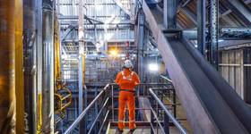
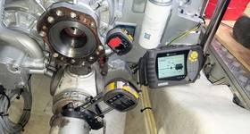
Left: Fig. 1 - Corresponds to model with purple triangle in Fig. 3. Right: Fig. 2 - Corresponds to model with orange triangle in Fig. 3. |
When an operator feels that they are experiencing a variation in equipment reliability from field to field for example, the issue may be related to a specific service provider, or certain companies carrying out maintenance procedures with more diligence than another. To be able to demonstrate this quantitatively, the operator can turn to a detailed reliability analysis of their extensive equipment test database.
 |
The following example shows the difference in mean time to failure (MTTF) of two different models of SSSV in gas producing wells to illustrate the variation possible. The outcome of the evaluation of the survivability of the equipment featured in Figure 1 is 75% over the coming five years (i.e. one in four of these installed valves will fail in five years), whereas the value derived from Figure 2 is over 90% (less than one in 10 will fail within five years).
 Engineers also need to be able to specify components that fail less frequently in operational conditions that are the same or close to those of their assets. They can use a reliability database subset of information that reflects their environmental conditions to select the components by vendor and model. This is particularly useful during an early phase of field development when there is little own-service experience.
It is also possible to compare failure information during the early years to identify whether the failure rate is indicative of a higher rate of burn-in failures. These may indicate manufacturing or material defects in certain equipment sources. This is illustrated in Figure 4, which shows a higher failure rate (steeper gradient of the failures curve) in the early life period.
 Subscribe