|
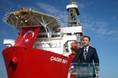
| Ceona Amazon (3D model) in full field development configuration with rigid and flexible pipe. |
A newbuild vessel, the Ceona Amazon, is due to enter the pipeline installation and construction market late in 2014. Ceona's Vibor Paravic explains stress and strain considerations for pipelay vessels.
The Ceona Amazon is London-based Ceona’s new concept in laying rigid pipe. The vessel’s design is based on existing s-lay and j-lay technologies, but with a new approach to how they are arranged on board the drill-ship style vessel.
The 200m-long, 32m-beam, Ceona Amazon is a multi‐construction vessel, able to install 16in. pipelines in up to 2500m water depth as well as accommodate pipe-in-pipe systems.
The vessel will enter service in Q1 2015, nine months after its flex-lay sister vessel, the Polar Onyx, entered Ceona’s fleet.
The Amazon’s hull was built at the Gdansk Crist Shipyard in Gdynia, Poland, before being shipped to Lloyd Werft Bremerhaven, in Bremerhaven, where the vessel is undergoing finishing. It will then move to Huisman’s yard in Schiedam, the Netherlands, where its two, 400-tonne capacity, heavy load cranes, and the 570-tonne pipelay tower will be fitted.
The Amazon has been designed tocombine proven s‐lay and rigid‐lay construction equipment, in a configuration that optimizes deck space and efficiency.
S-lay
The vessel will be able to carry 8500-tonne of rigid pipe on/below deck, like an s‐lay barge, which is 50% more than her nearest competitor. Instead of laying the pipe over a stern stinger, it will be deflected forward, around a deck aligner wheel.
The pipe is then guided up and over a second aligner wheel, at the top of a dual flex-lay/rigid‐lay tower. The pipe is straightened, in a conventional straightener, and then handled by two tensioners, with a combined 570-tonne top tension capacity.
S‐lay construction, where pipe stores are regularly replenished by barge, ensures maximum operational pipe-laying time at sea, and eliminates costly spoolbase construction and maintenance costs, and associated vessel transits.
Rigid-lay
In rigid-lay, the Amazon will have a 2‐4km/day lay rate. The vessel’s 200m length and 32m-beam, combined with the dual-tensioner tower, situated over a central moonpool, will maximize the operational sea state envelope, and provides access for handling cumbersome pipeline, end terminations and inline tees.
The aft deck area space created (with carousel below) is then suitable for construction tasks, using two active heave compensated deepwater mast cranes, with an 800-tonne combined lifting capacity.
Stress strain considerations
The most important consideration for a pipe lay vessel is the extent of accumulated plastic strain that the pipeline experiences, as it is repeatedly bent and straightened. This should be as low as possible, particularly for deepwater applications.
The extent of the accumulated strain and ovalising of the pipeline cross section depends upon the radius through which it is bent and the number of times it has been bent. The larger the bend radius, the smaller the ovalization and strain.
Accumulation of plastic strain is best illustrated graphically, using a basic strain formula to evaluate the cumulative plastic strain arising from the repeated bending and straightening cycles to which the pipe is subjected during the spooling‐on and associated lay processes.
On the Amazon, following s‐lay welding, the pipeline is moved aft by its 75-tonne deck tensioner and is bent around the 18m-diameter stern deck aligner wheel (O-A). During this forming process, the stress and strain in the pipeline increase in a linear elastic fashion, until the yield point is reached. After this point, the stress remains more or less constant, but the strain continues to increase, until the pipe bend radius matches that of the aligner wheel.
The pipe is held to the formed radius of the deck aligner wheel by the tension in the pipeline. If that tension were to be removed, the pipe would elastically spring back slightly but would not be straight, i.e. it would retain a residual curvature.
As the pipe continues to move around the aligner wheel, and into the free‐span section, it is then effectively pulled straight by the line tension (A-B). First, the elastic stress is relaxed and then the stress again increases (in the negative direction), as the pipe straightens, until the yield limit is reached. Thereafter, the strain continues to increase to a maximum that depends on the tension applied. As such, the pipe forms plastically, from its bent shape, until it almost looks straight, effectively reverse bending using the pipeline tension.
The wheel-forming process is then repeated as the pipeline passes over the tower aligner wheel (B-C). Finally, the pipe is drawn from the aligner wheel (C-D) and then passed through the straightener (D-E), inducing the correct degree of reverse bending to entirely remove the remaining residual curvature. When the pipe exits the straightener, it is straight, and both the stress and the strain have come full circle back to the starting point.
The accumulated plastic strain is a record of the sum of the plastic strain elements experienced by the pipeline during the cycle. The strain magnitude depends on the number of, and diameters of, the forming equipment items involved.
These strain steps also occur in reeling vessels, forming onto the reel (O-A), unreeling to the tower aligner wheel (A-B), passing over the aligner (B-C), passing into the straightener (C-D), and being straightened (D-E).
Because these steps are similar, the Amazon can be compared to other vessels in the current fleet, in terms of how much strain and ovality is put into the pipe by the installation vessels.
The Amazon’s deck aligner wheel and tower aligner wheel are identical, with an 18m diameter, equal to the reel of the Seven Oceans and greater than most other pipelay systems.
The existing vessels were all compared using their respective wheel/reel diameters and aligner wheel diameters. Classical and first principle formulas were used in order to ensure the comparison was on equal footing.
Calculations show that for the three pipe sizes considered, the three Technip vessels (Deep Energy, Deep Blue and Apache II) generate the lowest accumulated plastic strain, and that the Amazon and Seven Oceans return identical results, almost matching that of the Apache II. The Falcon, Seven Navica and remaining vessels, produce progressively larger accumulated plastic strains, due to the smaller reel/aligner diameters.
The ovalisation experienced by the Navica and Falcon borders the industry accepted 3% for the largest pipe size considered of 16”. The Amazon and Seven Oceans match closely with the Apache II, and all three produce ovality levels close to the industry leaders Deep Energy and Deep Blue.
 Vibor Paravic is Vice President Technology at Ceona. He has more than 20 years' engineering experience. He has been involved in all aspects of subsea engineering including detail design, subsea construction, and pipelay, covering projects globally. He has an MSc in Mechanical Engineering from the University of Houston.
 Subscribe