|
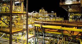
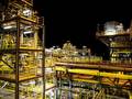
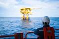
| Typical offshore deepwater field development. Image from INTECSEA. |
Abaqus FEA helps INTECSEA deliver durable pipe solutions for deepwater oil producers. Kip Hanson reports.
It's not that the world is running out of oil. The problem is getting to what remains of it, at a prive that consumers can swallow. A September 2013 oil market report from the International Energy Agency (IEA) said that global demand for oil and liquid fuels will rise to 93MMb/d in 2014, an annual increase of more than 2%. This comes at a time when most experts agree the days of “easy” oil are over. Petroleum companies are now forced to drill in areas deeper and more remote than ever before.
In the case of deepwater production, this means very high and unpredictable pressures coupled with severe temperature gradients both inside the pipe and out. Worse, the wellstream fluids coming from these depths are increasingly sour, a corrosive witch’s brew containing high levels of hydrogen sulfide, CO2, and volatile organic compounds that make short work of regular carbon steel pipe. The oil industry has responded with calls for better pipeline material.
Clad pipe has been used in high-strain environments for decades. By metallurgically bonding a thin layer corrosion resistant (CRA), typically 316L or Alloy 625, to the inside of C-Mn structural steel pipe, a robust combination of strength and corrosion resistance is formed.
However, clad pipe suffers from long lead times and high cost. Sherif El-Gebaly, lead pipeline engineer at INTECSEA, a global company within the WorleyParsons Group, says that clad pipe can cost 10 times that of regular C-Mn Steel. “An alternative is CRA mechanically lined pipe using a weld overlay at the ends,” he says. “This is both easier and quicker to manufacture, presenting cost savings of 30% over clad pipe.”
However, concerns over the weld overlay to liner interface joint have prevented wide use of CRA mechanically lined pipes due to the technology readiness level (TRL) not meeting operator requirements. INTECSEA has been working to resolve and increase the confidence in CRA mechanically lined pipe for use in harsh environments.
 |
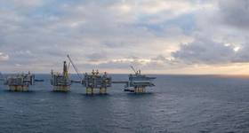
| Image 2: Abaqus FEA model of pipe girth weld. Image from INTECSEA. |
Making the weld stronger than the pipe
Pipe sections are manufactured in lengths of about 12m, called pipe joints. These joints are then girth welded together end-to-end to create a pipeline. For mechanically-lined pipe, each CRA joint is slid inside a carbon steel joint and plastically expanded in the radial direction to ensure a tight fit between the carbon steel and the liner. The fitted CRA joint is shorter in length, leaving a distance of about 50-150mm at each end; this gap is filled with a weld overlay of a CRA material, bonding the CRA layer to the carbon steel pipe and enabling the joint-to-joint girth weld to be performed.
“Girth welds are critical,” said INTECSEA global technology director Philip Cooper. “Some of these installation vessels are running a million dollars a day. The weld joints are inspected prior to lowering the pipe into the sea, and if repairs have to be made at this point, it can seriously impact production rates.”
 |
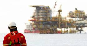
| Image 5: A bird's eye view looking inside a heated pipe that has been reverse loaded with a severe bending strain. Several ripples can be seen in the upper left hand corner of the photo. Image from Paul Montague. |
Regardless of how much pipe gets laid in a day, environmental and safety considerations mandate zero tolerance for failure once the pipeline is in the water. This is because deepsea flowlines are subject to tremendous stress as they transport a mix of oil, water, gas and sand from the wellhead to the offshore storage facility (FSO) or onshore processing terminal. This fluid alternately heats and cools the pipeline, causing expansion, bending and potential buckling. High-velocity slugs of liquid and gas within the pipe create vibration, leading to fatigue. Even the weight of the pipe itself as it crosses the uneven terrain of the seafloor is a cause for concern.
“The movement of the pipeline under production conditions is similar to your garden hose when you turn on the tap,” Cooper said. “You’ll get wiggling and sideways motion due to the pressure. This is why fatigue performance and strain capacity in this environment is so important.”
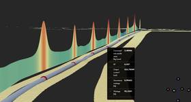
The oil industry demands thorough testing of any component used in deepsea oil production, and CRA- lined pipe is no exception. Because of its two-layer design, some experts were concerned over the possibility of ripples forming in the liner material under bending stress which presents a risk of premature failure (Image 1). Equally important was ensuring the integrity of the girth welds used for the weld overlay-style pipe.
But since sticking your head inside a 12in. diameter pipe one mile under the ocean is clearly not an option, INTECSEA design engineers have been employ- ing realistic simulation with Abaqus finite element analysis (FEA) software from SIMULIA, the Dassault Systèmes 3DEXPERIENCE application.
 |
| Image 1: FEA analysis of pipe response to stress. The diagram at the top shows the pipe at rest. As bending force is gradually applied, ripples begin to grow in the CRA liner. At the bottom, the pipe is beginning to buckle. Image from INTECSEA |
Visualizing deepsea conditions with Abaqus
FEA lets the team query the geometry and behavior of computer models of their pipe designs, simulating every condition from production to performance thou- sands of feet below the ocean surface. “We’ve been using Abaqus for the past decade or so,” Cooper said. “Over the last few years it’s really become our preferred tool for pipeline design. On top of that, many of our customers show a preference for Abaqus. It’s more or less a standard in this industry.”
El-Gebaly’s team had a number of factors to consider when setting up their Abaqus FEA models to predict lined pipe and weld behavior. “One challenge was a potential problem with under-matching,” he said.
“Imagine that you have two 12m long pieces of pipe and you’re welding them together (Image 2). The weld is basically just a ring, one that is stronger than the pipe on either side. Normally when you bend the whole system, you don’t have to worry about this small ring, you’re concerned more with the pipe materials.
“But if at some point the yield strength of that ring becomes less than that of the pipe on either side—for example, under certain high-temperature operating conditions, or where the consumable selected for welding exhibits a lower yield strength at certain temperature than the base material—the joint will actually become more flexible than the pipe and then all the strain flows into it. FEA helped us investigate such cases.”
There were other scenarios to check within the assembled pipeline itself. Aside from the garden-hose example described by Cooper, El-Gebaly was concerned with the development of ripple- type deformations induced in the liner layer during spooling and subsequent installation. “You have to understand the behavior of liner under bending moment, the wrinkling onset conditions, as well as the fatigue performance of the girth weld during the installation and design life,” El-Gebaly said.
|
|
| Image 3: Temperature is an important component in pipe performance and simultaion models replicating such performace require accurate data capture. Here, a pipe is wrapped in a heating blanket as it is brought up to 130C, replicating the effect of high temperature well fluids |
A day in the life of lined pipe
Much of the data needed to accurately capture such behavior with FEA models comes from extensive land-based testing.
Sections of CRA-lined pipe are put through numerous physical tests, monitored by strain gages used to measure axial and radial force, and piezoelectric and Bourdon gages to monitor pressure. Hydraulic rams, heating coils, and various other devices are then applied to sections of pipe to simulate the severe conditions at the bottom of the sea.
Using test data, combined with industry-standard material properties for X65 pipe lined with 316L CRA, INTECSEA created Abaqus FEA models of their pipe and carried out parallel virtual tests. Multiple simulation runs were performed using both pressurized pipe models replicating production conditions, and unpressurized ones that reproduce the conditions expected during transport and installation.
Reducing both development costs and long-term risk
Results to date have been promising. Ultrasonic tests show close correlation between FEA and real-world behavior, demonstrating that INTECSEA’s pipe and weld designs are performing well. Better yet, internal rippling of the CRA liner has been demonstrated to be minimal for certain design conditions, even when subjected to high buckling forces and temperatures of 130°C. (Image 5)
 |
| Image 4: CRA-lined pipe wrapped in insulating material. This test demonstrates a pressurized and heated pipe placed under a 1.5% strain load. |
According to El-Gebaly, once the models have been fully validated, using Abaqus will certainly help INTECSEA reduce real-world testing costs. But there’s more to it than higher front-end savings: FEA helps to assess design risks and possible failures. “For pipelines, it only takes one joint to fail for a release-of-contents event to occur, so it is crucial to assess every failure mechanism,” he said.
Kip Hanson is a freelance writer and manufacturing consultant in Tucson, Arizona. With more than 30 years’ experience in manufacturing and business management, he has written on a wide range of topics, including machining and fabrication, consumer products, oil and gas, CAD/CAM/FEA and ERP systems. Prior to his current position, Kip worked as the IT director for a global manufacturing company, and also spent a number of years business consulting with a mid-range ERP software and services provider.
 Subscribe