|
|
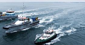
Fig. 1: Illustration of riser acceleration vs. wave height. Images from 2H Offshore. |
Michael Long Ge and Himanshu Maheshwari explain a new methodology developed by BP and 2H Offshore to monitor fatigue on drilling riser systems.
In support of its commitment to safe and reliable operations, BP has been continuously developing a program to assess and maintain structural integrity for offshore drilling risers and conductors. In conjunction with 2H Offshore’s riser experts, BP developed a new fatigue monitoring methodology for drilling riser systems due to both wave and vortex-induced-vibration (VIV) damage.
BP has been monitoring structural response, including the fatigue damage, of riser systems in the Gulf of Mexico over the past 10 years. The structural response of multiple BP drilling risers and conductors are monitored using a number of acceleration data loggers and/or strain gauges.
A drilling riser is subjected to fatigue due to VIV, direct wave loading and vessel motions. To date, the focus for riser systems has predominantly been on determining fatigue damage due to VIV, since it and its effects on structural response are generally not a well-understood phenomenon. The measured fatigue damage due to VIV is typically calculated by mode shape reconstruction in the frequency domain, using the logged accelerations at various riser locations.
In addition to VIV fatigue, direct wave loading and vessel motions also contribute to the total fatigue damage. Sometimes wave fatigue may have more contributions than VIV fatigue damage, especially in shallow water depths and/or wave dominant conditions, such as hurricanes or winter storms. Figure 1 shows the relation between median RMS accelerations from the loggers along the riser and significant wave heights for a period while the riser is connected. It indicates a strong correlation of the measured median acceleration to wave. In this example, the maximum acceleration occurs on October 2nd, when the highest wave is also observed. The contribution of wave induced fatigue to the total fatigue damage is material and should be considered. To confirm the long-term fatigue integrity, it is necessary to determine fatigue due to both wave and VIV effects.
 |
| Fig. 2: Illustration of riser acceleration and curvature |
To take full advantage of the accumulated data for the monitoring program, a new fatigue monitoring methodology was developed. The methodology is using an analytical solution which accounts for damage due to both wave and VIV effects. With the new method, the measured acceleration data is converted into curvature, and then fatigue damage along the length of riser and conductor is calculated. This new methodology has been validated with both finite element analysis (FEA) and field data, and sensitivities to various parameters have been considered.
Analysis methodology
Riser acceleration is measured at a number of locations along the drilling riser system using motion data loggers. An analytical transfer function is derived to correlate the accelerations with the curvature of riser at the data logger locations. Assuming an acceleration data logger is installed at point B on a riser segment OA, as illustrated in Figure 2, the lateral acceleration a(x,t) is converted to the curvature using wave theory.
The transfer function is shown in Figure 3 along with the spectrum of the acceleration. The transfer function decreases with increased frequency, but remains relatively stable within the wave frequency range. Once the curvature time traces are known, stress time traces at the outer fiber of the riser pipe can be calculated based on riser dimensions and material properties.
New methodology is validated based on the finite element analysis (FEA) and field monitoring data.
 |
|
Fig.3: Transfer Function; Fig. 4: curvature comparison between FLEXCOM and analytical transfer method; Fig. 5: Variation of curvature standard deviation along riser length |
FEA is performed with specified input parameters, including environment data, riser configuration, mud weight, and tension. The outputs from FEA, especially the curvature along the riser string, are compared with results by the new methodology. The advantage of using FEA results to validate the methodology is that there is no noise and g-contamination in the accelerations and curvature time traces. There are also no uncertainties in the added mass and tension values. In addition, the validation can be carried out along the entire riser length instead of the logger locations.
 |
|
Figure 6: Riser Configuration for Staggered Joints |
An example deepwater riser configuration is used for FEA validation. A sea state with a significant wave height (Hs) of 6.56ft and a peak period (Tp) of 7.6 seconds is selected, since this sea state causes the largest fatigue damage on riser compared with other sea states from the metocean data. An added mass coefficient of 1.0 is considered for both the FEA and analytical transfer methodology (ATM).
A time trace of the curvature obtained from the analytical transfer method is compared with that obtained from FEA output, as shown in Figure 4. The curvature from the analytical transfer method matches well with FEA results for both the phase response and the curvature amplitudes.
The standard deviations are also compared along the riser length in Figure 5. The standard deviations of the curvature from FEA and the analytical transfer method agree along the riser length except the top 60ft zone that is close to the tension ring where the joint dimension is modeled slightly different in both methods. The top slick joints below the outer barrel consist of three pup joints: 40ft, 20ft and 5ft. The top element in Figure 5 is right below the outer barrel. The outer barrel OD is 25in, while the top pup joint has a drag OD of 23.4in. The drag OD the pup joints are chosen according to given dry and wet weight. The ATM method considers the properties at the interface of two different joints, which cause the results to be slightly different from the FEA method.
Field monitoring data validation
The validation of the methodology is also conducted using field measurement data. A set of by 12 motion loggers and two strain sensors are deployed at specific locations along the riser string. The measured accelerations are used as input to calculate curvature data by the analytical transfer methodology, which are then compared with the ones obtained from the strain gauge sensor at the same location.
The field-deployed riser configuration with staggered slick and buoyant joints, is shown in Figure 6. During the operation period, the drilling water depth is 6823ft with a top tension of 1685kips and a mud weight of 10.8ppg. The accelerometer and the strain gauge sensor are located on the bottom end of the 6th joint above lower flex-joint, about 5ft above the joint interface, as shown in Figure 7. The structural OD at the sensor location is 21in, while the inertia OD of 41in considers the presence of riser fins and auxiliary lines.
A three day wave dominant response period is selected for field data validation. Figure 8 shows the comparison of the curvature between the analytical transfer method and the strain gauge measurement. The stress derived from the strain gauge sensor is used to obtain the field curvature. The curvature time traces from the two sources match well, as zoomed between 200 and 600 seconds. The low frequency contents below 0.05Hz in the curvatures are filtered.
The strain gauge sensor is located approximately 5ft above the joint interface, and the joint below this slick joint is buoyancy joint. Field added mass and equivalent OD are not clearly known, especially at the location of the strain gauge sensor which is located 5ft above the transition between the buoyancy joint and the slick joint with fins. At this location the hydrodynamic effects of buoyancy and slick joints coexist. Therefore, it is challenging to define the correct hydrodynamic properties for this formulation at this elevation. The standard deviation of the curvature around the pipe circumference is compared between the analytical transfer methodology and that from the field strain gauge. As shown in Figure 9, the analytical transfer methodology matches the field data well, considering a drag diameter of 54in and an added mass coefficient of 1.73 for the slick joint.
Sensitivity and discussion
The curvature using field data is affected by signal noise, sensor orientation, local tension at the strain gauge sensor, the added mass, and the alternation of the buoyancy and bare joints. The added mass and associated hydrodynamic diameter are not known, therefore the sensitivity of the curvature from the ATM to these parameters is studied in this section.
 |
|
Figure 7: INTEGRIstick curvature sensor mounted on slick riser joint with fins associated hydrodynamic diameter are not known, therefore the sensitivity of the curvature from the ATM to these parameters is studied in this section. |
The sensitivity of the curvature standard deviation to added mass coefficient in the analytical transfer method is shown in Figure 10. The added mass coefficient is given as 1.0 for all riser joints in FEA, while it is varied between 0.5 and 2.0 in the analytical transfer method. The variation of standard deviations at six typical locations of the riser (A through F) is plotted against the added mass coefficient, as shown in Figure 10. Compared with the base case with Ca=1.0, the curvature standard deviation of the slick joints (A, B, C, D) increases about 3.6% for every increment of 0.1 (or 10%) in added mass coefficient, while increases about 4.8% for buoyant joints (E and F).
Measured riser tension and mud weight in the field may not always be 100% accurate. Hence, the curvature standard deviations are also compared for different top tensions. The top tension of about 1800kips is increased and decreased 50kips and the corresponding curvature change is shown in Figure 11. For a constant tension change along the riser length, the curvature standard deviation shifts by a constant. Every 1% of tension change in the riser leads to about 1% of change in curvature standard deviation.
Field measured accelerations contain the portion due to gravity (g-contamination), and it may affect the curvature accuracy if not well understood. By retrieving the riser tilt angle at any given location from the FEA model, the acceleration of gravity, g, can be projected into the accelerations as controlled g-contamination, which is compared with the accelerations from FEA output to analyze the percentage and sensitivity. In time domain, accelerations with and without g-contamination are compared and shown in Figure 12. A maximum g-contamination of 14% of the acceleration standard deviation is found along the riser length. The g-contamination is found negligible. Note however that for applications where higher dynamic riser angles are expected, the g-contamination can be removed through the use of angular rate measurements.
Conclusions
To take full advantage of the accumulated monitoring data, a new fatigue monitoring methodology was developed using analytical acceleration to curvature transfer function to account for the fatigue damage due to both wave and VIV effects.
This new methodology has been validated very well with a finite element analysis (FEA) method, by comparing curvature distribution. The advantage of using FEA results to validate the methodology is that there is no noise, g-contamination, and added mass and tension uncertainty in the accelerations and curvature time traces.
 |
|
Figure 8: Curvature Comparison between Analytical Transfer Method and Field Data In Time Serial; Figure 9: Curvature Comparison between Analytical Transfer Method and Field Data On Cross Section |
Comparing with field measured data, the results show that the calculated fatigue is sensitive to added mass and drag diameter, but not g-contamination. With a 54in-diameter drag and an added mass of 1.8, the proposed method matches well with the measured field data. A standardized approach for selecting the added mass coefficient and hydrodynamic diameter is the subject of ongoing work.
For future work, both acceleration and strain measurements from a riser system with continuous buoyancy or slick joints are preferred to better understand the effect of the total added mass, which is dependent on the added mass coefficient, Ca and the drag diameter. In addition, a more detailed and complicated CFD simulation may be conducted to investigate the actual drag affect and added mass effect. Extra strain sensors on different locations and a non-staggered riser configuration would also assist in further validation of this methodology.
 |
|
Figure 10: Sensitivity of Curvature Standard Deviation to Added Mass Coefficient; Figure 11: Variation of Curvature Standard Deviation with Tension; Figure 12 G-Contamination Effect on Acceleration Standard Deviation |
Acknowledgments
The authors thank the management of BP for permission to publish this paper. In addition, the authors wish to express thanks to 2H Offshore engineers who did the data analyses documented in this paper.

Michael Long Ge is subsea riser engineer. He has worked on a wide range of projects for BP in the Gulf of Mexico, including engineering, design, inspection, maintenance, monitoring, and integrity management. He holds a MS in mechanical engineering from University of Florida and a BS in engineering mechanics from Shanghai Jiao Tong University.

Himanshu Maheshwari is a senior engineering specialist at 2H Offshore in Houston. He has extensive experience in delivering riser integrity management and monitoring programs including project management, system engineering, instrumentation, installation and data management. Maheshwari has a MS in mechanical engineering from Texas A&M University.
 Subscribe