Laser scanning with real-time results using offshore-approved tablets is coming, say Carl Bennett and Stewart Buchanan.
 |
|
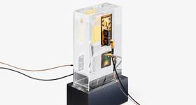
Linking together data from multiple surveys to create whole platform virtual model Images from Wood Group ODL. |
Aging offshore assets, in the North Sea and elsewhere, require routine maintenance and inspection to ensure their continued integrity. Mobilizing designers and engineers offshore to view and measure equipment and structures takes up scarce bed-spaces needed by maintenance and operations personnel.
An increasingly used alternative is laser scanning, to create precise virtual models of a platform, known as point-clouds. These provide onshore engineers with the accuracy (less than 3mm across an entire platform) and detail required to design and fabricate items such as spools, vessels and skids. In turn, construction teams can install the new items safely, without encountering any clashes or failures-to-fit.
Laser scan technology has been available to the oil and gas industry for over a decade. However, in the last five years, the use of digital color photography to produce full color point-clouds has further enhanced its use. The color images assist designers, engineers, project managers, and construction coordinators, with visualizing exactly what is on the installation, and are ideal for platform familiarization, or considering design options at the start of a project.
A full facility first
In 2012, Wood Group ODL was tasked with its first whole, colored-platform scan. The platform topsides are about 12,200-tonne, comprising 27 individual modules on seven levels, giving an indication of the scale of the facility. The offshore phase of the survey required 65 days on the platform with two surveyors.
To put this in context, most surveys undertaken require 7-14 days offshore, with a single surveyor. Since the DCS team was formed about four years ago, it has undertaken surveys on 36 offshore platforms and floating production, storage and offloading vessels, and three on-shore facilities, mostly in the UK sector.
The scanning was undertaken module by module, and each set of scans were combined into one database, shown in Figure 1. For this project, the scan required 1.4 terabytes of data. Some 220GB of raw data was gathered during the survey from the total stations, laser scanners and digital photography.
How it’s done
For a full platform laser scan, a survey team creates a platform control network, to enable all laser scans to be linked together into a single virtual model.
 |
|
A 3D visualization developed from scan data. |
Using the control network, each surveyor performs the laser scans and panoramic color photography in locations where at least five control network targets can be seen by the laser scanner.
Leica HDS6200 instruments are currently used, with Nikon digital SLR cameras fitted with fish-eye lenses capturing color images, and a Nodal Ninja to ensure the camera is in the same aspect as the scanner. Each up to five minute scan, performed under ISO 9001:2008, covers a 360 degree floor to ceiling volume and collects some 50 million pixels, to provide measurements which will meet the tolerances required by fabricators. For a clash check within a module there will be 50 scans typically, and a scan of a platform deck will require hundreds of scans.
The raw data is processed, using Leica’s Cyclone software, to create a single point cloud; a 3D display of the laser returns from the scanner in one position. The scanner is designed to ignore signals returned from beyond 80m, as the accuracy is degraded above that distance. However, during processing, the ODL dimensional control survey (DCS) team filters out all scan data beyond 15m, improving the accuracy, reducing the amount of data to be processed, and removing returns from distant spools or modules that would show up as noise.
The digital photographic imagery is processed using PTGUI software, which takes 30 images from each survey point and stitches them into a single panoramic image. From this image, six flat images are created, to show the front, both sides, behind, above and below the survey point.
The colored point clouds are then registered, using Cyclone, to ensure the data from each scan properly aligns. Finally, Leica’s CloudWorx program, and a CAD (computer aided design) program, is used to apply a coordinate system to the database.
Data for decommissioning
The laser scan data on the full platform scan was required to model all cut zones and separations to plan a proposed method of decommissioning. In addition, the surveyors were able to use the point-cloud to identify the nearest flanges, valves that could be disconnected without requiring cutting.
The layered CAD drawings, in conjunction with the model TruView, provide the as-built information necessary to identify and detail all systems that require cuts in each specific cut zone, allowing complete module separation.
The decommissioning study team would not have been able to complete the module separation scope to a useful level of detail if they had to rely on existing drawings and documentation. Additional offshore survey trips were not an option, due to a drilling campaign underway on the platform.
Further benefits
3D scan data can also be crucial for brownfield modifications. Most platforms in the North Sea have a plant design management system model, which provides 3D information based on the platform’s design drawings. Using the point-cloud data, they can then compare their design with the as-built dimensions on the platform, which will take into account any changes made to the original design.
Colored point-cloud databases provide a source of highly accurate information, which can be shared easily between disciplines, teams, project offices and even third-parties, via web portals. Portals can be layered with data from other sources, such as maintenance plans, asset integrity data, inspection reports and images, creating an integrated system to assist duty-holders in maintaining a safe and productive asset.
Point-cloud data can also be processed to create training environments, providing operators, maintenance engineers, and construction crews with realistic training before mobilizing offshore.
More applications and easier use is coming, however. Up until recently, significant computing power has been required to handle the large terabyte-size files created. Now, laptop and desktop processing speeds and storage capacity have become sufficiently affordable to make the process cost-effective and capable of delivering survey data in an acceptable time. In the future, we could see scans from handheld devices then viewed live on offshore safe tablets.
However, there is still a place for traditional surveys using instruments known as Total Stations, for smaller jobs such as closing spools, where speed is of the essence, and for replacement of like-for-like items. For surveying larger volumes, or complex pipe-runs over several decks, laser scanning is a more efficient and effective method.
Future
The ability to process larger amounts of data faster is bringing point-cloud data to fabricators or operators more quickly. Hand-held scanners are becoming lighter and more accurate, and when linked to hand-held tablets will enable data-gathering to be carried out in near real-time.
It will not be long before it will be even more cost-effective to undertake whole-platform scans, and use hand-held scanners to provide detailed information on areas of interest, such as corrosion, signs of wear, or tie-points for new or replacement systems.
Using intrinsically safe tablets will enable the onshore and offshore teams to share information almost immediately, and for initial designs to be virtually superimposed over the actual platform structure and equipment to confirm the suitability and practicality of the design.
Laser scanning combined with digital photography is a well-established technology that is currently providing significant benefits to the oil and gas industry. As the technology matures and develops it will play a vital role in the safe and efficient operation and maintenance of oil and gas assets, both onshore and offshore.

Carl Bennett joined Production Services Network (now Wood Group PSN) in 2006 after a 20-year career in the Royal Air Force. Since joining Wood Group PSN, he has worked as a project engineer supporting a major client and was assigned to the Royal Dutch Shell Asset Integrity Process Safety Management program in the Netherlands. He holds an MBA from the Aberdeen Business School.
Stewart Buchanan joined Wood Group ODL in December 2013 as Global Head of Sales and Marketing. Stewart is responsible for the development and implementation of the global sales and marketing strategy to drive ODL’s business plan.
 Subscribe