An alternative view of pipework vibration management by Neil Parkinson, technical director at AV Technology.
 |
|
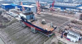
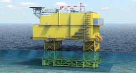
Complex offshore pipework. Images from AV Technology |
Some incidents are guaranteed to make headlines, never more so than at control of major accident hazards regulations and offshore installations safety case regulations sites, which have the ability to turn even the smallest incidents into disasters.
The UK Health & Safety Executive (HSE) reports that more than 20% of offshore hydrocarbon leaks are caused by piping vibration and fatigue.
In 2012, 431 serious incidents were reported, of which nearly 30% involved hydrocarbon release. More than 50 were classed as major, and 33 in total were attributed to pipework failure. Vibration-induced fatigue clearly represents a serious risk category, but how exactly were these pipelines broken?
If asked to break a paperclip, most people would probably bend it back and forth, or perhaps rub it against another surface until it wore through. One might pull it until it snaps, or use tools to cut it through. Although pipework is far larger and more complex, individual molecules of steel behave the same way in a pipeline as they do in a paperclip – meaning that pipelines can fail as easily as a paperclip can be broken. Bending a paperclip back and forth has the same effect as low-cycle fatigue in pipework, leading to vibration fatigue over time. Rubbing a paperclip to wear it down through friction is equivalent to fretting in pipework. Static overloads and pressure surges in pipelines are similar to pulling a paperclip until it snaps, while both can be subjected to mechanical damage.
Back-and-forth vibration of pipework is one of the most common causes of failure. Mechanical excitation, flow-induced pulsation, changes in surge or momentum, acoustic-induced vibration, or cavitation and flashing are all common vibration-induced failure mechanisms. But how much vibration is significant?
The Energy Institute (EI) publication “Guidelines for the Avoidance of Vibration Induced Fatigue Failure in Process Pipework”* contains an assessment chart to determine whether pipes are likely to suffer fatigue, based on frequency and velocity of movement – and the levels for concern might be surprising. In fact, problematic vibration may not even be visible to the human eye as even at dangerous levels, prolonged movements of only 0.5mm can produce fatigue failure. For EI assessments, pipework movement must be measured in units of velocity at different frequencies. At 25Hz (1500rpm) for example, pipework vibrating at 8mm/s would place it in the “concern” range, while anything above 40mm/s is a definite problem.
 |
| Energy institute chart T7-2. |
The EI guidelines cover proactive and reactive assessments, and aim to ensure compliance with statutory duty as well as improving safety and reliability, reducing liability from leakage, and minimising plant downtime. Proactive assessments can be used to routinely evaluate all existing pipework on site to ensure that best practice has been adopted and to identify possible areas of concern, as well as assessing the feasibility of planned extensions to pipework. Reactive assessments follow, to further investigate known vibration issues or troubleshoot actual failures within both mainline pipework and small bore connections (SBC).
Although vibration amplitudes are barely visible and velocities are relatively low, the cumulative effect over time can be significant – especially as problems can go unnoticed until a dangerous failure suddenly occurs. However, as vibration is well understood, fatigue failures are easily preventable with a range of retrofit solutions available for a host of applications.
As the solution to vibration depends on the excitation mechanism, thorough inspection must be undertaken before determining the corrective action. There are six key phases to achieving pipework vibration assessments in line with requirements of the EI guidelines:
The qualitative assessment phase involves calculating the likelihood of a vibration-induced fatigue issue, taking into account fluid energy, flow velocities and cyclic operation as well as the construction quality of infrastructure. This may include assessment of process machinery and types of valves as well as supporting structures. It also assesses the chance of flashing or cavitation, and includes a calculation process for scoring likely excitation factors – which are combined with conditional and operational factors to predict the likelihood of failure for each pipe branch.
 |
| Braced pipework |
Visual inspection is a quick and effective method of identifying potential areas for concern and flagging up areas for improvement relating to pipe infrastructure. This may include installing more effective pipe supports or replacing worn or damaged supports, proper bracing of SBCs, avoiding fretting and poor geometry, and allowing for thermal expansion of tubing.
In the basic piping vibration measurement phase, specialist engineers will first use a single axis accelerometer connected to a portable data collector to take initial vibration levels, ranging from 1Hz up to 300Hz. These measurements are presented as vibration amplitude versus frequency and enable the vibration to be classified as acceptable, concern or problem, based on EI guidelines.
If, following the basic measurement phase, vibration is found to be at concern or problem level, or for pipework with a higher frequency vibration of more than 300Hz, the next phase is based on specialist measurement techniques. A variety of more in-depth tests are deployed depending on circumstances, including: dynamic strain measurement and fatigue analysis; experimental modal analysis; operating deflection shape analysis; and dynamic pressure (pulsation) measurement. Engineers also have a choice of specialist predictive techniques, applying sophisticated modeling tools and multi-channel instrumentation systems to assess in more detail the dynamics of specific pipelines throughout their lifecycles. Specialist predictive techniques include finite element analysis, computational fluid dynamics, and pulsation and surge analysis.
The final stage of any pipework assessment is to recommend corrective actions to reduce vibration levels and the likelihood of future vibration-induced fatigue failures. Although one solution to pipework fatigue is to remove the excitation mechanism altogether, this may be quite intrusive, requiring modification of the process conditions or the pipework geometry. As this disrupts production and may involve temporary shut-down, generally a non-intrusive retrofit solution is preferred as a means of providing increased resistance to vibration.
 |
|
Visco-elastic damper |
Some corrective actions can be very straightforward. For example, it is very common for pipelines to rest on supports without any additional protection against fretting damage, in which case a secondary “doubler” plate can be installed for additional support and strength without modifying any processes. However, unsuccessful or incomplete attempts at supporting pipework can result in no reduction of vibration or even an exacerbation of the problem. SBCs are frequently braced to the deck or nearby structures, for example, but to adequately counteract vibration they should in fact be braced back to the parent pipe. Bracing solutions can also be fitted in the wrong place, supporting the pipe itself rather than the main mass such as a valve, while poorly maintained bracing can loosen and return the pipework to its original level of excitation.
Another common mistake is to brace the pipework in only one plane, where vibration can cause movement in several directions. The most effective bracing system will be able to accommodate any geometric alignment of SBC, with a stiff truss design to resist movement on any plane. Similarly, for mainline pipes, visco-elastic dampers are effective in all degrees of freedom as they provide dynamic damping movement in all directions and over a wide frequency range. Another option for mainline pipework is a dynamic vibration absorber, which when tuned to the same frequency and direction as the problem vibration, will resonate to the same level out-of-phase in order to cancel it out. This is especially useful if there is no steelwork nearby on which to attach a visco-elastic damper.
Although pipework vibration can be difficult to visually detect, knowledge of EI Guidelines and safe limits as well as an understanding of the six assessment phases and the most effective corrective actions can prevent the kind of vibration-induced pipework fatigue which can break a pipeline and hit the headlines.
* 2nd edition 2008, current edition. ISBN 978 0 85293 453 1.

Neil Parkinson is a chartered engineer with more than 30 years’ experience in vibration management and structural asset integrity. He has held the position of technical director for AV Technology since 1993. He holds a BSc in engineering science from the University of Warwick and was elected a fellow of the Institute of mechanical engineering in 2011.
 Subscribe